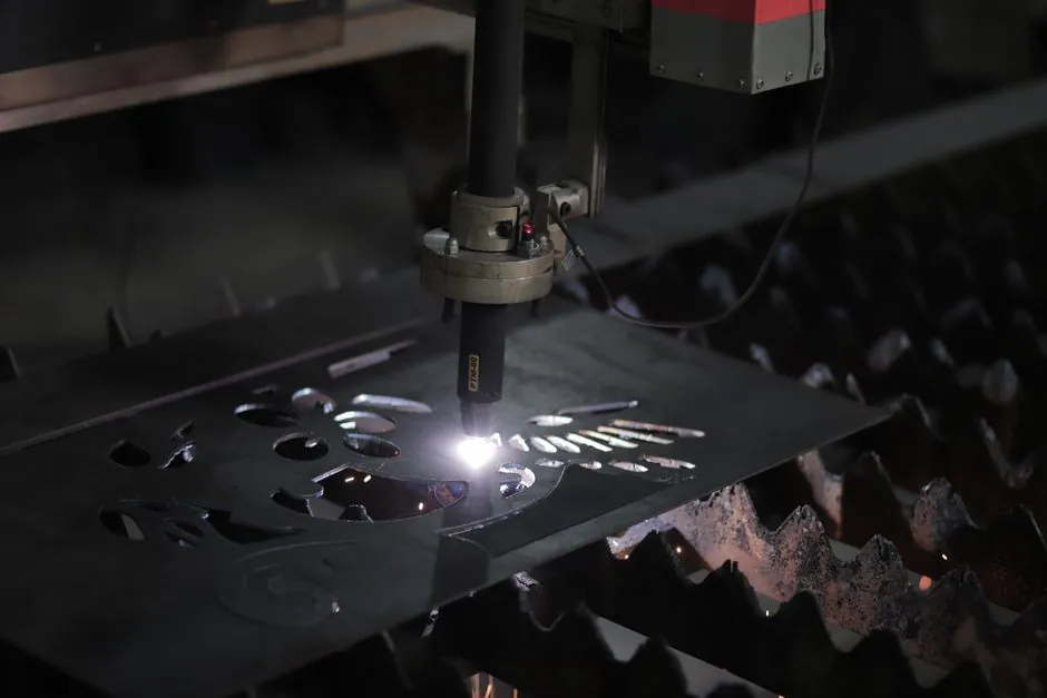
Industrial cameras and laser profile scanners solve overlapping but fundamentally different measurement problems, and the wrong pick inflates integration cost by 30–60% on a typical conveyor-inspection cell [S1][S2].
An industrial camera captures a 2D image (or a 3D point cloud when paired with a projector) in one exposure, while a laser profile scanner emits a laser line and triangulates a single cross-sectional profile that must be stitched by motion over time [S1][S4]. Output, frame architecture, and lighting tolerance therefore diverge before any software decision is made [S1][S4].
Core Technology: Triangulation Line vs Full-Field Image
A laser profile scanner projects a laser stripe at a fixed angle onto the target; a CMOS or CCD receiver in the head records the stripe's deformation, and one profile is emitted per scan cycle at rates of 1 kHz to 140 kHz on current 3D sensor platforms [S1][S6]. The scanner reconstructs a 3D point cloud only after the part or the sensor moves, so coverage and scan time are coupled.
An industrial camera, by contrast, captures a full 2D frame in a single exposure. In industrial camera deployments for inspection, resolution commonly runs from 1.6 MP to 20 MP at 30–160 fps over GigE Vision or USB3 Vision links, and 3D data is derived only when a structured-light pattern projector is co-bundled [S1][S6]. The architectural consequence: cameras deliver instantaneous full-field data, whereas laser profiler heads deliver high-density cross-sections that must be aggregated.
Resolution, Speed, and Profile Density
Laser profile scanners are documented at single-digit micron resolution in the cross-line axis on premium heads, with up to 4,096 points per profile and profile rates up to 140 kHz on the AT 3D series GigE Vision / GenICam 3D / NBASE-T platform at 5 Gbit/s [S1][S6]. On a moving conveyor at 1 m/s, a 10 kHz profile rate yields 100 microns of cross-line spacing per kilohertz, which is the physical resolution floor the system integrator must budget for.
Industrial cameras resolve in pixels, not microns. A 5 MP camera with a 10 micron pixel pitch and a 50 mm lens at 0.5 m working distance resolves roughly 100 microns per pixel at the object, comparable in some cases to a mid-range laser profiler on a 2D axis but with no native height axis. Single-shot 3D snapshot cameras exist, but they require more processing time per capture and are more efficient for 2D image processing than 3D scanning when the geometry is complex [S4].
Lighting Tolerance and Ambient Robustness
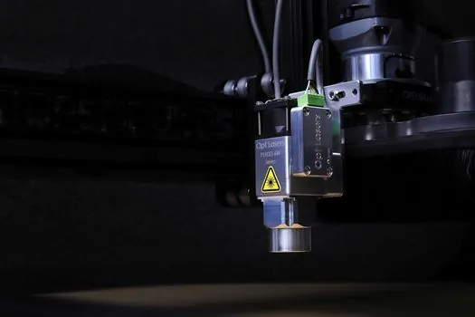
Laser profile scanners carry their own illumination: the laser line is many times brighter than factory ambient, so the receiver filters to the laser wavelength and rejects background light. Laser triangulation sensors are therefore described as less affected by ambient light and resilient to lighting variations in industrial cells [S1]. Structured-light and white-light scanners, in contrast, depend on the projector's radiant intensity relative to the room: white-light structured-light scanners can turn up sensor gain in difficult ambient lighting but at the cost of noisier, less accurate data, and outdoor or high-ambient cells can swamp the projected pattern entirely [S8].
Industrial 2D cameras with controlled LED bar lights behave predictably in dark or dim cells but lose contrast in uncontrolled sunlight or in cells with arc-weld flash, where band-pass filters and fast electronic shutters become mandatory. White-light 3D scanners, including structured-light and laser-line systems with broadband receivers, are also limited by the contrast level of the projector against the surface being scanned [S8].
Surface Adaptability: Shiny, Dark, and Multi-Material Parts
Laser triangulation handles diffuse surfaces well, but specular and transparent parts still require specialized optics. Blue-light laser scanners (typically 405–450 nm) are widely specified over red (635–660 nm) for shiny metals and electronics because shorter wavelengths scatter more efficiently off the surface and reduce speckle; the same physics is why laser level tools for construction migrated to green/blue sources for visibility on dark substrates. [S7]
Industrial cameras, especially 3D laser-line and structured-light heads, suffer on shiny or dark surfaces because the projected pattern either hot-spots or absorbs. White-light scanning is constrained by the contrast level of the projector on the target, and a black rubber gasket on a steel carrier will return a weak signal regardless of camera or scanner [S8]. For multi-material production lines (rubber-on-metal, glass-on-plastic), the integration effort to tune exposure per part often outweighs the sensor cost difference.
Decision Matrix: When to Specify Each
For dynamic, in-line dimensional verification on a moving conveyor with 50–500 micron tolerance, the laser profile scanner is the default: 10 kHz+ profile rate, single-digit micron Z-resolution, and built-in ambient-light rejection match the use case [S1][S2][S6]. Cost of ownership sits in the mid-thousands to low-tens-of-thousands USD per measurement point, and basic pass/fail configuration lands under 2 hours with vendor documentation [S2].
For 2D defect detection (surface scratches, label presence, print quality, color verification), defect classification, and any task where the deliverable is a pixel image rather than a height map, the industrial camera wins on cost, ecosystem, and processing-tool maturity. For full 3D shape capture of static parts where scan time is flexible, structured light wins on coverage per exposure; laser profiling wins when the part is large, the environment is uncontrolled, or the geometry is complex [S1][S5]. For hand-held metrology where the operator sweeps the device, structured-light and laser scanners both have product lines, but laser triangulation is more robust in challenging working conditions and on complex mechanical parts [S5].
For high-mix robotic cells (welding, sanding, deburring) the choice pivots on path-generation speed. Structured-light scanners capture a full 3D shape in one or a few exposures, which shortens robot cycle time per part but inflates sensor cost; laser profilers mounted on the robot arm deliver higher cross-line precision and reject ambient light better, but require coordinated motion and are more sensitive to vibration [S1].
Integration Effort, Standards, and Cost
Vendor-documented basic setup and pass/fail configuration for a laser profiler is under 2 hours, while advanced tasks (custom filter design, multi-sensor fusion, PLC logic integration) take 1–2 days of hands-on training when the team has no prior machine vision experience [S2]. Industrial cameras sit on more mature software stacks (OpenCV, Halcon, MVTec, vendor SDKs) and a deeper integrator pool, which usually compresses integration time for 2D jobs but extends it for 3D point-cloud work where the team has to build the matching pipeline themselves.
Both product classes now ship over GigE Vision with the GenICam 3D standard for profile data, and 3D laser profile sensors support NBASE-T at up to 5 Gbit/s alongside GigE Vision for high-throughput 3D image capture [S6]. Industrial cameras use the same GigE Vision / USB3 Vision / CoaXPress transport family, which means a shared PLC, vision-controller, and cabling layer across both architectures; in practice, an end-of-line cell mixing 2D color inspection cameras and 3D laser profile heads on a single GigE switch is a routine architecture in 2025–2026 builds. For deeper guidance on cross-protocol selection at the controller layer, see this Top Industrial Ethernet Companies 2026 protocol map.
Failure Modes and Common Sizing Mistakes
The three most common sizing errors on laser profile scanners are: (1) under-budgeting standoff distance, which inflates the laser line's apparent thickness and caps Z-resolution; (2) ignoring the cross-line spacing implied by conveyor speed and profile rate, which silently degrades the X-resolution to millimeters; and (3) specifying red lasers on shiny metal and accepting the resulting drop-out rate. For a baseline reading on mounting geometry and the trade-off between working distance and line width, the laser level encyclopedia page lays out the same optical geometry used in triangulation. [S2]
For industrial cameras, the recurring failures are: choosing a sensor with too few pixels for the required field of view (forcing a smaller part envelope than the line actually needs); relying on auto-exposure in cells with arc-weld flash or strobe lights (motion blur); and treating a 2D camera as a 3D scanner by adding a single projector, when a structured-light pattern plus calibrated stereo is required for any usable height data [S4][S8]. The single-shot 3D profile capture that laser sensors deliver out of the box remains faster than camera-based snapshot sensors for 3D tasks, especially on complex surfaces [S4].
Spec a laser profile scanner when the deliverable is height or cross-section on a moving part, ambient light is uncontrolled, and tolerances are sub-100 microns. Spec an industrial camera when the deliverable is a 2D image, color or texture inspection is the goal, the part is stationary, and budget per station is below the cost of a laser head plus controller. For cells that need both, plan a shared GigE Vision backplane and a single vision controller from the start, and revisit the 3D camera vs. industrial camera split only after the conveyor and lighting design are locked.