A modern industrial robot is a 6-functional-group machine: manipulator (mechanical structure), drivetrain, controller, sensor suite, end-effector and the safety/interface layer that ties the cell to the plant bus [S4]. Standard ISO 8373:2021 defines an industrial robot as an automatically controlled, reprogrammable, multipurpose manipulator programmable in three or more axes, and most spec sheets engineers see on a panel builder's desk today still map cleanly onto that definition [S1][S4].
Decomposing the bill of materials against that six-group frame lets a buyer compare apples to apples across SCARA, delta and articulated families without getting lost in marketing tier names. The remaining third is split between harnesses, sensors, the end-effector and safety I/O — the part of the BOM most often under-engineered on first prototypes.
Manipulator Frame: Castings, Linkages and Bearing Stack
The manipulator frame is welded steel or aluminium-alloy castings, joined by a chain of RV reducers and harmonic-drive gearheads, with output flanges carrying a wrist that ends in an ISO 9409-1 mechanical interface [S1][S3].
Crossed-roller bearings support the wrist output because they handle combined axial, radial and moment loads in a single compact unit, which is why sizing a wrist against pure axial load is a common spec error. For buyers who need a refresher on how moment load, life and rail length interact in a crossed-roller stage, the crossed-roller guide sizing logic breaks the moment-life equations down. Most six-axis arms reach repeatability of ±0.02-0.05 mm at the wrist, gated by the backlash of the wrist-stage harmonic reducer (commonly ≤10 arc-sec) [S1][S3].
Drivetrain: Reducers, Servo Motors and Drives
A six-axis arm is therefore six motor-drive-reducer triplets, sized so the joint torque exceeds the worst-case dynamic load by roughly 1.5-2× [S1].
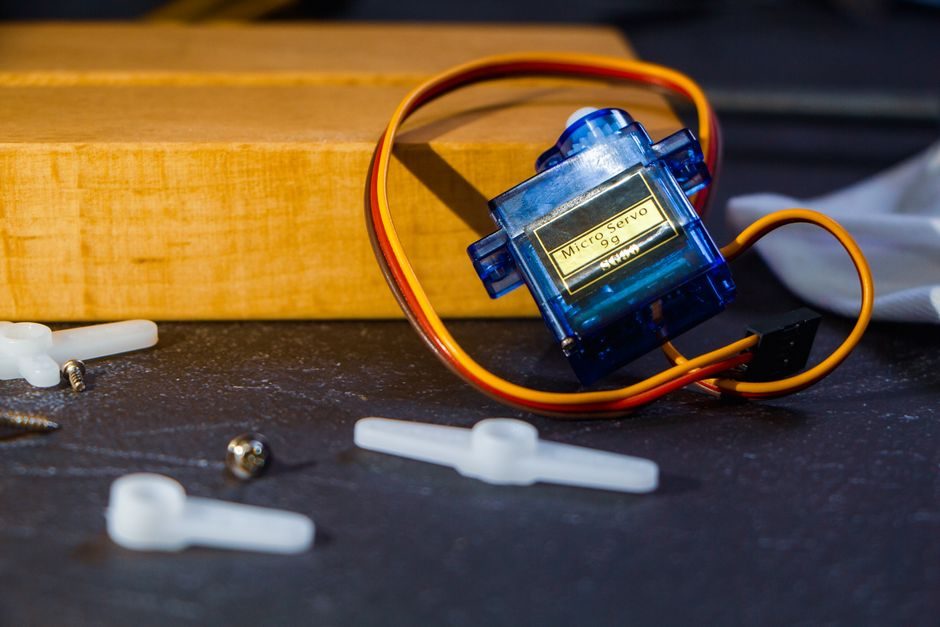
Servo choices on a modern BOM are almost always permanent-magnet AC brushless with absolute encoders of 17-23 bit resolution; the drive sits in a centralised cabinet (legacy architecture) or, increasingly, on the joint as a fully integrated servo-gearhead module [S2][S3]. Robot-control competence is essentially the competence to coordinate these six loops — modelling, trajectory generation and feedback — at cycle rates of 1-4 kHz on a typical industrial controller [S2]. Sourcing note: the reducer tier is dominated by Japanese makers (RV) and a narrower harmonic-drive supply base, so second-source qualification usually forces a re-check of backlash, torsional stiffness and lubrication interval against the OEM's published spec [S1][S3].
Controller Stack: CPU, Servo Bus and Safety CPU
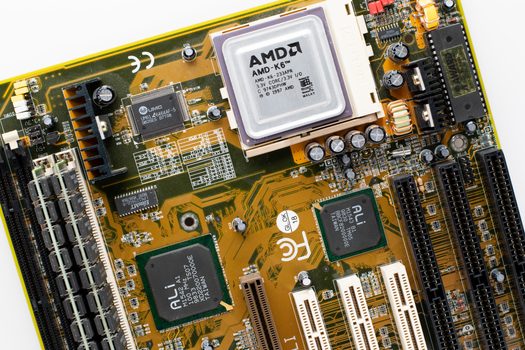
The controller is an industrial PC or dedicated motion CPU, real-time OS (VxWorks, RT-Linux or proprietary), a servo-communication fieldbus (EtherCAT, PROFINET or CC-Link IE TSN being the 2026 baseline) and a separate safety CPU that handles STO/SS1/SLS over FSoE or PROFIsafe [S2][S3]. Cycle times on the servo fieldbus sit in the 250-1000 µs range for EtherCAT and PROFINET IRT, which is what lets a six-axis arm follow a path error of well under 0.1 mm at 1 m/s TCP speed [S2].
Programming interfaces are teach-pendant plus a high-level language, with the dominant 2026 choices being ROS 2 industrial, Python or vendor DSLs that compile to the same trajectory engine [S2]. Robot control therefore has to be modelled, simulated and verified offline before code reaches the cell — a fact that pushes buyers to specify simulation toolchains (Gazebo, Isaac Sim, vendor-native) as part of the controller BOM, not as a separate line item [S2]. For readers cross-referencing adjacent motion-control BOMs, the linear-module spec and sourcing logic article covers the same servo-bus + drive architecture from a different mechanical frame.
Sensor Suite: Encoders, Force/Torque and Vision
The sensor stack is a three-layer pyramid: joint absolute encoders (17-23 bit) on every axis, a six-axis force/torque sensor at the wrist on collaborative and machining robots, and 2D/3D vision on the cell bus [S1][S3]. Wrist-mounted F/T sensors are typically rated 50-2000 N force and 5-200 Nm torque depending on payload class, with sampling rates of 1-8 kHz for force-control polishing or assembly work [S1].
On the perimeter side of the BOM, safety laser scanners and/or safety mats feed the safety CPU over the same FSoE/PROFIsafe channel; the cell-level wiring rarely exceeds 24 V, with safety devices meeting ISO 13849-1 PL d / Cat 3 as the most common spec floor [S1][S3]. Buyers should not confuse perception sensors (vision, F/T) with the safety-rated devices in the interface layer — the cost, mounting and certification paths are different and a frequent source of inspection findings on first-article cells. If the cell needs industrial cameras, the industrial camera selection band and the industrial borescope band both apply, depending on whether the optics are doing inspection or part-location duty.
End-Effector and Tool-Changer Subsystem
The end-effector is the only part of the BOM that changes with every cell, which is why most system integrators spec a quick-change tool-changer on the ISO 9409-1 wrist flange instead of bolting the gripper directly [S1][S4]. Pneumatic grippers (single- or double-acting) are the default for pick-and-place, electric grippers for force-controlled assembly, and vacuum grippers (with ejector or blower) for sheet and packaging work [S1].
End-effector I/O is typically 8-16 pneumatic ports plus 8-24 electrical signals, fed through the changer body so the robot can swap tools in 2-5 seconds without re-homing [S1]. The compressed-air side of this subsystem is where most energy-waste findings originate, since a 6 bar unregulated supply to a gripper that only needs 3 bar wastes a measurable share of the cell's pneumatic budget — the air solenoid valve spec band article covers the matching valve and supply-pressure logic in detail. If the cell uses industrial adhesive dispensing as its primary process, spec the dispenser and the curing stage as part of the same end-effector package.
Safety, Interface and Standards Mapping
The safety and interface layer is a discrete BOM group: E-stop hardware, safety controller, perimeter devices (scanners, light curtains, mats), a teach-pendant with 3-position enable switch, and the cell-level I/O block on PROFINET, EtherNet/IP or CC-Link IE TSN [S1][S2]. The standards stack most buyers map against is ISO 10218-1/-2 (robot and cell), ISO 13849-1 (safety-related control, PL a-e) and ISO/TS 15066 (collaborative operation, where applicable) [S1].
Wiring discipline is 24 VDC signal, 400/480 VAC three-phase power for the controller cabinet, and category 6A or fibre for the cell-level bus; harmonic filters and line reactors are common on the cabinet input when the cell shares a feeder with VFD-driven conveyors [S2][S3]. Buyers should not collapse safety I/O and process I/O onto a single block — the wiring, segregation and labelling rules differ, and a Safety I/O shortage at the quote stage is the single most common reason cell deliveries slip by 4-8 weeks. A complementary teardown view of the same six groups against 2026 price bands is in Industrial Robot BOM: Six Functional Groups, Core Components, Sourcing Bands.