
An industrial robot production line is engineered, not assembled: it is a stack of electromechanical subsystems formalised under ISO 8373, anchored by a main controller, vision arrays, drives, end effectors, rugged connectors and a power regulation block [S2]. Designing one means locking payload, reach, degrees of freedom and cycle time first, then mapping those numbers onto a plant-floor layout that also passes safety, ergonomics and ROI gates [S3].
Done correctly, a robotised line recoups capital through repeatable quality, lower direct labour, and faster changeovers; done without an upstream needs analysis, the same hardware becomes a stranded asset. The engineering work sits in the middle: deciding which tasks belong to which robot class, and which stay with automatic molding line-style fixed tooling or human operators.
What "industrial robot production line design" actually covers
ISO 8373 frames an industrial robot as an automatically controlled, reprogrammable, multi-purpose manipulator programmable in three or more axes, and that definition is the starting line for any design conversation [S2]. A production line built around one or more such robots is therefore a coordinated system: incoming part handling, the robotic work cell itself, inter-cell transport, downstream inspection and packaging, plus the MES/ERP data spine that schedules all of it [S3].
NorComp's design guide breaks the robot itself into six subsystems that must be specified together: control panel with main controller module, sensor and vision arrays, electromechanical drives with end effector and manipulator, power regulation and management, rugged connector and cable assemblies, and networking/communications [S2]. Each subsystem carries its own vendor selection, EMC and reliability constraints, and a layout failure in any one of them propagates back to throughput. Michale Automation's project framework adds a sixth layer: integration with ERP and MES, which the integrator calls the difference between a "machine on a floor" and a "production system" [S3].
The six-stage design workflow engineers actually run
Michale Automation's published methodology walks designers through needs analysis, concept, detailed engineering, simulation, procurement/integration, and commissioning, with a continuous ROI loop running underneath [S3]. Each stage has a verifiable deliverable, and skipping any one of them is the documented cause of most retrofit projects.
Stage 1, needs analysis, captures product dimensions, sensitivity to environment, planned volume, future expansion headroom, available technologies, safety obligations, and demand volatility [S3]. Stage 2 turns those into a process flow and rough cell layout. Stage 3 selects the robot class, end effector, vision, conveyor and safety devices, and produces a cycle-time budget. Stage 4 simulates cycle time, reachability and collision envelopes in software before any steel is cut. Stage 5 procures and integrates, including the controller-to-MES hookup. Stage 6 is on-site commissioning with takt-time acceptance tests against the ROI model. The same six-stage spine is what engineers reuse when they later bolt a new molding line onto an existing robotic cell.
Selection criteria: matching robot class to the task
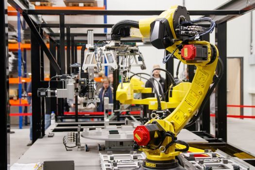
The single most consequential decision is task-to-robot class mapping, because once a six-axis articulated arm is anchored to a pedestal, its 2 m reach envelope and 10–500 kg payload rating dictate every downstream layout choice [S2]. NorComp lists payload, range of motion, and the type of motion (linear vs rotary) as the three first-pass filters, with environment and reliability class following [S2].
The mainstream options line up against four decision criteria as follows. 6-axis articulated robots (e.g. SIASUN, Omron) cover the widest task range, mid-to-high payload, and the largest footprint per cycle. SCARA robots win on high-speed pick-and-place at sub-10 kg payload and a small horizontal envelope. Delta (parallel) robots dominate ultra-high-speed sorting and packaging where the part is light and the conveyor is fixed, a configuration that maps cleanly onto a conveyor sorting line upstream and downstream. Cartesian/gantry robots carry the heaviest payloads over long travels but at lower acceleration. The picking rule is therefore simple: match reach and payload first, then cycle time, then footprint, then integrator ecosystem.
Operating environment and reliability class
Industrial robots must be specified to survive power surges, ESD events, extreme temperatures, corrosive or toxic atmospheres, and mechanical vibration or shock, per NorComp's environmental checklist [S2]. That is why mainstream robot OEMs target circuit board assemblies at IPC Class 3 or higher, the same acceptance class used in aerospace and medical, and pair them with ruggedised, overmoulded, locking connectors on the power and data harnesses [S2].
Two practical consequences follow. First, any cell sited near a foundry, a plating line or an outdoor pad needs an IP65+ wrist and sealed cable exits from day one; retrofitting sealing after the fact is more expensive than buying it. Second, vibration and shock budgets must be quantified against the robot's mounting frame, because the controller, the vision camera and the cable loom all share the same mechanical ground. A line frequency furnace cell, for example, imposes continuous low-frequency vibration that a clean-room electronics cell does not, and the connector choice changes accordingly. Standard reference: ISO 8373 for robot definitions and terminology, IPC-A-610 Class 3 for electronic assembly acceptance.
Automation, integration and the data spine
Robotic cells earn their ROI when they are wired into the factory's data layer, not just its power layer. Michale Automation's published position is that robotisation and automation improve process repeatability, quality and safety, but the visible lift comes from MES/ERP integration that exposes cycle counts, OEE, faults and recipe changes to planning [S3]. The integrator's stack typically runs OPC UA from the robot controller up to an MES, with ERP above for orders and BOMs.
The design implication is to specify the controller's supported fieldbuses and upper-layer protocols at the concept stage, not at commissioning. PROFINET, EtherNet/IP and OPC UA are the three most commonly demanded; controllers lacking the required stack get deselected before any cycle-time simulation is run. Designers also need to budget for cybersecurity segmentation of the robot VLAN, which has become a board-level topic in plants bound by IEC 62443.
ROI, safety and the failure modes to engineer out
ROI on a robotic cell is typically recovered through higher OEE, lower scrap and reduced direct-labour cost, with payback windows that Michale Automation's framework sizes against the simulated cycle time versus the manual baseline [S3]. A useful sanity check: if the simulated takt time does not beat the manual station by at least the factor the integrator's case assumes, the cell fails its own ROI test before the first part is produced.
Failure modes to engineer out include reach-envelope collisions (caught in simulation, not on site), end-effector changeover downtime (designed down with quick-change plates), cable fatigue at axis 3 and 6 (specified to a minimum bend radius and strain relief), and safety-zone violations (covered by ISO 10218-compliant safeguarded space, light curtains and speed-and-separation monitoring). Operators must be retrained on the new cell, because most documented incidents occur during commissioning, cleaning or fault recovery, not during normal cycle. For a deeper dive into one adjacent trade-off, see the Delta Robot vs AGV selection map, and for cells where welding is the dominant process, the Welding Robot supply and lead-time map lays out the 2026 delivery risk. Foundries mixing robots with sand-handling should also review the resin sand line envelope, because the two cells share floor space and vibration profile.
Track these signals over the next planning cycle: published cycle-time benchmarks from robot vendors (refreshed quarterly, used to re-baseline the ROI model), and the IEC 10218 / ISO/TS 15066 update cadence for collaborative-cell safety rules, which directly affects whether a fenceless layout is still permissible. Engineers who revisit the original six-stage design document against those two inputs every 6–12 months tend to catch obsolescence before it catches the production schedule.