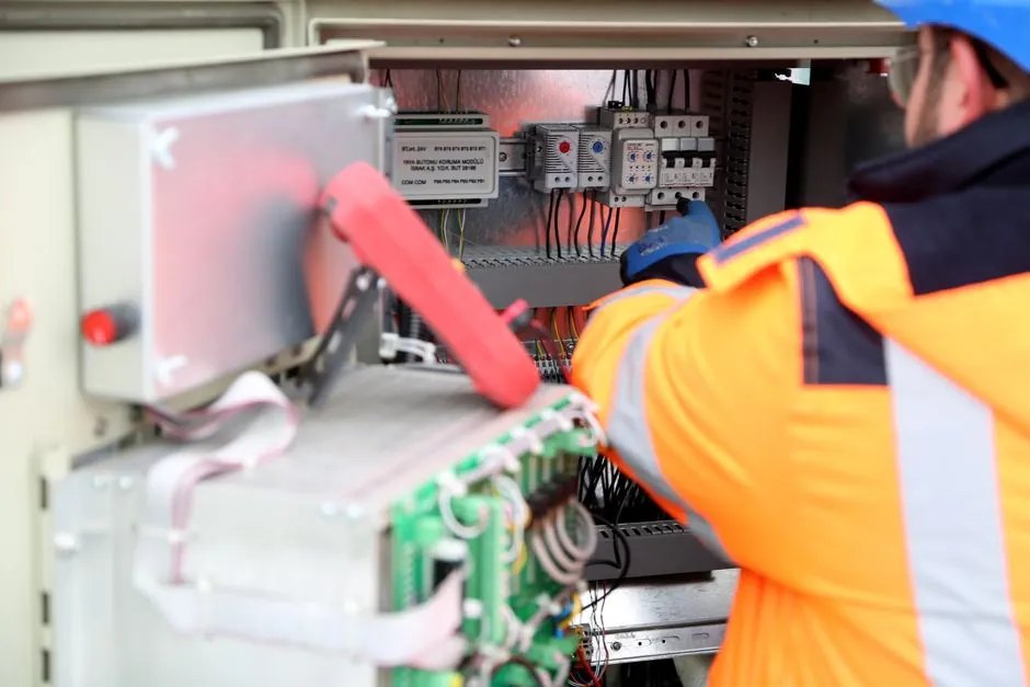
Integrated PLC control on a hydraulic power unit (HPU) packages the motor starter, proportional or servo valve drivers, pressure and temperature transmitters, and safety logic into one pre-engineered, factory-tested cabinet rather than wiring these elements separately in the field [S1]. The combined architecture typically runs at 24 VDC logic, uses 4-20 mA analog or HART signaling for sensors, and exposes the PLC to plant networks over Ethernet, PROFIBUS, or CANopen [S1][S7].
HPUs are spec'd across a wide pressure envelope, from low-pressure machine-tool units in the 50-100 bar band up to 200 bar pulse systems controlled by a Phoenix Contact Nanoline-class controller with 0-10 V analog outputs and 0-5 V analog inputs [S3]. At the high end, an integrated hydraulic power unit such as the IMI Remosa RHPU couples a high-performance servo valve and redundant hydraulic components with an onboard controller wired into the plant safety system for fail-safe valve actuation [S4].
Cabinet Architecture and I/O Map
An integrated HPU control cabinet is built around a single PLC control chassis selected to match machine complexity, from compact 16-point CPUs for simple start/stop and pressure-switch logic to redundant processors for safety-instrumented functions [S6]. The PLC drops into a backplane with discrete input modules for pressure and level switches, analog input modules for 4-20 mA pressure and temperature transmitters, and analog output modules driving proportional valve current loops.
Field-side wiring from the cabinet typically uses 4-20 mA pressure and temperature transducers, 24 VDC discrete I/O, and communication channels such as HART, Ethernet, Wi-Fi, and CANopen on programmable SMART-series units [S1][S7]. Real-world industrial examples show analog I/O scaled 0-10 V out and 0-5 V in on a Phoenix Contact Nanoline PLC controlling a 0-200 bar hydraulic pulse generator with four independent pulse trains [S3].
Communication Protocols and Field Signaling
Communication on a modern integrated HPU defaults to Ethernet TCP/IP at the supervisory layer, with field-level options including HART, PROFIBUS, CANopen, Foundation Fieldbus, and Wi-Fi depending on the OEM [S5][S7].
Vendors routinely publish protocol coverage: Flotech lists "all common communication protocols supported" alongside redundant sub-systems and motor starters, while Hydronit specifies PWM power outputs plus CANbus, Wi-Fi, Ethernet, and HART channels on its SMART programmable HPUs [S5][S7]. This protocol breadth matters because the hydraulic power unit often has to hand off data to a higher-level safety PLC for ESD and turbine trip voting.
Safety, SIL Ratings, and Redundancy
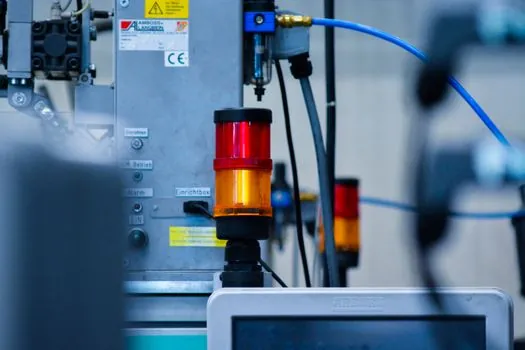
Safety integrity is the non-negotiable axis. Catalog HPUs with integrated control are commonly quoted at SIL 2 with options to upgrade to SIL 3 in the safety-logic subsystem [S1]. The IMI Remosa RHPU reaches SIL-relevant redundancy by combining a high-performance servo valve with redundant hydraulic components and an onboard controller that interfaces to the plant safety system, so a single failure cannot prevent the valve from reaching its fail-safe position [S4].
For emergency-stop and safety-circuit integration, the cabinet hardwires an E-stop chain, motor overload, and a safety relay or safety PLC rated for the target SIL [S1]. A FRL unit on the pneumatic supply to a pneumatic-hydraulic pulse skid will also be interlocked into the same safety chain to remove motive force on trip. Selecting between a hardwired safety relay and a dedicated safety PLC is driven by the number of safety I/O and the required diagnostics coverage, not by HPU pressure class.
Power, Enclosure, and HMI Specs
Integrated HPU panels are designed for global deployment: catalog voltages typically include 220 V, 380 V, 415 V, and 440 V, with enclosure ratings from IP55 up to IP65 for dusty or washdown environments [S1]. The human-machine interface side is a 7" to 15" color touchscreen, sized to the cabinet door and the number of process graphics [S1].
Real-time monitoring covers pressure, reservoir level, temperature, filter differential pressure, and motor current; the PLC logs alarms, latches trips, and exposes them via remote diagnostics over Ethernet [S1]. Flotech's catalog entry for fully PLC-controlled HPUs reinforces the same scope: pressures, levels, and flow rates monitored, with redundant sub-systems, motor starters, and bespoke local electrical control on the options list [S5].
Selection Criteria: Which HPU Architecture Fits
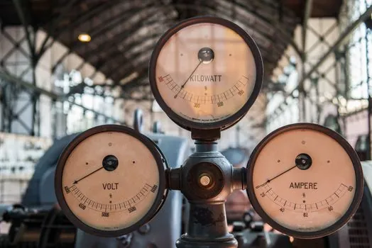
Selection between a basic, a redundant, and a fully programmable HPU is driven by three variables: the safety integrity level required by the process, the number of closed-loop control loops, and the I/O count for sensors and valve drivers. A simple start/stop HPU with pressure-switch interlocks can be handled by a compact PLC with 8-16 discrete I/O, while a servo-driven valve actuator with closed-loop position control needs analog I/O modules and a faster scan cycle, often under 10 ms. [S3]
For comparison, three common integrated HPU control tiers line up as follows. Tier 1 is a non-redundant PLC with hardwired safety relay, IP55 enclosure, and 4-20 mA sensors, typical of standalone machine-tool power packs. Tier 2 adds an HMI touchscreen, HART or Ethernet communication, and a soft-started or VFD-driven motor for energy savings. Tier 3 layers in a redundant PLC pair, SIL 3 safety logic, redundant hydraulic components, and a servo or proportional valve with closed-loop position feedback, as on the IMI Remosa RHPU [S1][S4][S5].
Uniteq's product data captures the same trade-off in one sentence: "The type of PLC varies between simple and more complex redundant PLC systems, dependent on the hydraulic power unit and customer specifications" [S6]. A practical hydraulic test actuator setup running on a bench benefits from Tier 2 at minimum so the test sequence can be programmed and replayed.
Programming, HMI, and Lifecycle
Programming environments track the controller brand. Siemens, Allen-Bradley (Rockwell), and Schneider Electric are the three most commonly listed PLC families on integrated HPU panels, with code written in ladder logic, function block diagrams, or structured text per IEC 61131-3 [S1]. Parallel-running threads on a single PLC create a reactive state machine, useful for sequenced pulse trains where each thread handles one independent pulse series with its own count, pressure, and timing parameters [S3].
Lifecycle considerations include spare-parts stocking for the PLC, firmware update paths, and the option of redundant power supplies and CPUs. Intelitek's PLC-controlled hydraulic systems training course targets exactly this skill set, covering ladder troubleshooting and HMI design for PLCMotion simulations, which mirrors the workflow a maintenance team will use on a live HPU [S2]. HMI design should follow ISA-101 high-performance HMI principles: trend screens for pressure and level, alarm summary, and one-touch acknowledgment, with a depth of screens kept under four clicks for any operator action.
For a process engineer specifying a new HPU, the practical signal that a vendor is serious about integration is the degassing unit being wired into the same PLC with a level switch and temperature transmitter, not bolted on with a separate controller. Watch for the next two signals: SIL 3 safety-PLC options becoming standard on Tier 2 builds, and OPC UA Pub/Sub over TSN replacing classical Ethernet/IP on new OEM panels through 2026-2027.