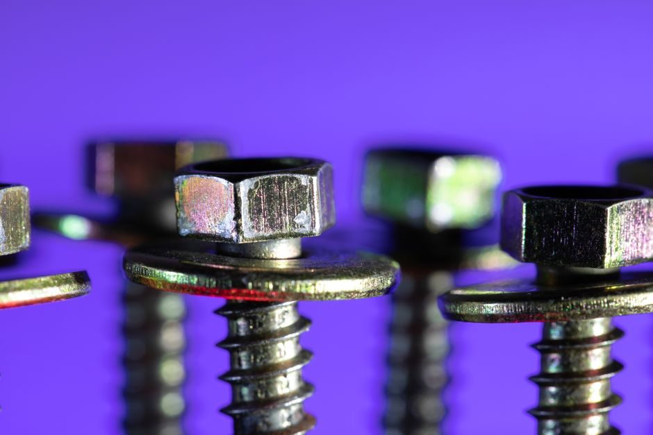
A lead screw is a threaded rotating shaft paired with a translating nut that converts torque into linear force at a fixed mechanical ratio defined by the helix lead [S4]. Classification of any lead screw rests on three independent axes: thread profile geometry, the friction interface between screw and nut, and the resulting self-locking characteristic governed by lead angle.
Engineers pick a type first by required positioning accuracy, axial load, duty cycle, and whether the load must hold position with the motor de-energised. A practical selection map combines those axes with the standard thread profiles that are actually stocked and traceable to ISO metric or imperial Acme/Square/Trapezoidal standards.
Thread-Profile Classification: Acme, Square, Trapezoidal, Buttress
Acme threads — with a 29° included thread angle — are the workhorse general-purpose lead-screw profile and are widely available in 1/2"-to-2" diameters as imperial Acme [S1]. The flank angle lets Acme nuts be cut easily and re-machined on site, which is why so many industrial jacking, clamping, and stage-rigging builds use it.
Square threads (0° flank angle) give the highest mechanical efficiency of any sliding profile because the load vector sits parallel to the thread flank, but the sharp crest is fragile and difficult to cut, limiting them to low-duty hand-actuated presses and slow jacks. Trapezoidal (Tr) threads, defined under ISO 2908 / DIN 103 for metric sizes, are the European functional equivalent of Acme and are the most common metric lead-screw profile; 8 mm-to-80 mm diameters are stocked, with multi-start leads available for faster travel. Buttress threads carry load on a single flank only and are specified for unidirectional heavy axial loads such as large valve stems and screw-down presses, where reverse loading is negligible.
Sliding vs. Rolling Element: Acme Lead Screws vs. Ball Screws
Sliding-contact lead screws (Acme, Tr, square, buttress) carry load through direct metal-on-metal contact between the screw helix and the nut threads [S3]. A Simscape Multibody model demonstrates that raising the coefficient of friction above the tangent of the lead angle makes the joint non-back-drivable, which is exactly why self-locking is a design property tied to friction and lead, not to thread profile alone [S3].
Ball screws replace the sliding pair with a closed loop of balls running between screw and nut raceways. Efficiency climbs from the 20-50% range typical of an Acme sliding nut to roughly 90% for a well-preloaded ball screw, and positioning repeatability drops into the 0.01-0.05 mm band. The trade-off is cost — a comparable ball screw is typically 3-5x the price of an Acme unit of equal diameter and lead — and the need for lubrication, seals, and contamination control. For a deeper dive into rolling-element drives, the ball screw reference covers load ratings, preload classes (P0/P2/P3/P5), and dynamic-capacity life calculations.
Self-Locking Behaviour and Lead-Angle Threshold
Self-locking in a lead screw is governed by the inequality μ > tan(λ), where μ is the thread/nut coefficient of friction and λ is the helix lead angle [S3]. Once the friction angle exceeds the lead angle, an axial load cannot back-drive the screw even with the motor de-energised, which is the property exploited in scissor lifts, medical beds, and telescope elevation drives where holding position without a brake is mandatory [S2].
Ball screws generally violate this inequality — efficiency of 90% means μ is too low to self-lock, so vertical or suspended loads need a fail-safe brake or a counterbalance. Designers choosing a sliding Acme unit for a vertical axis typically run lead angles of 3-7° (metric Tr 8x1.5, Tr 10x2, Tr 12x3) specifically to keep tan(λ) below the steel-on-steel μ of 0.10-0.15. Lubricated bronze or polymer nuts can drop μ to 0.05-0.08, which raises the lead-angle ceiling to roughly 4° before back-drive becomes a risk; this is the engineering reason a switch from greased steel to polymer Acme nut sometimes unlocks unexpected sag in an existing axis.
Nut Material Classification: Bronze, Steel, Plastic, and Polymer
Nut material is the second axis of classification and drives both friction and wear life. Cast bronze (C932, C954) nuts on hardened-steel screws are the default for low-to-medium speed industrial service where lubrication is dependable; they tolerate surface temperatures to roughly 150 °C and present μ around 0.10-0.15 when grease-lubricated. [S2]
Plastic and polymer nuts (acetal/Delrin, PTFE-filled compounds, nylon) drop μ into the 0.05-0.08 band and run clean — important in medical, food, and laboratory equipment where oil contamination is unacceptable [S2]. They sacrifice load capacity and heat tolerance, typically rated to continuous service around 80-90 °C and dynamic loads an order of magnitude below a comparable bronze nut. For a fundamental overview of the sliding-screw family including nut-material selection charts, the lead screw encyclopedia page indexes the major types against typical duty cycles. Applications in waste-water and bulk-material handling — where long screw runs are paired with rotating augers — often appear in the same procurement specification set; see the screw conveyor page for the through-shaft auger variant.
End-Fixity, Mounting, and Drive Configuration Classes
How a lead screw is supported at its ends changes its load class as much as the thread itself. A screw fixed-fixed at both ends (tension/compression) reaches the highest critical speed and lowest deflection; simply-supported (pinned at both ends) cuts both by roughly 40%; a cantilevered (fixed-free) screw should be specified only for short, low-rpm motion. End-fixing is a procurement-specification line item: bearing stack, pillow-block part numbers, and angular-contact vs. deep-groove bearing choice must be written into the RFQ or commissioning drifts between units. [S2]
Drive configuration forms a separate sub-classification. Direct-drive couplings between motor and screw minimise backlash but transmit any side-load from misalignment into thrust-bearing preload. Belt- and gear-reduced drives trade rigidity for speed multiplication and are common when the motor's natural rpm is too high for the lead. A pre-engineered linear actuator package bundles screw, nut, bearings, and drive into a single part number — useful for OEM buyers who do not need to spec the screw stack themselves but want to keep the screw-selector questions in the supplier's hands.
Operating Limits: Load, Speed, PV, and Duty Cycle
Three numeric envelopes decide whether a given lead screw type will survive its duty cycle: dynamic load capacity C (kgf or kN), permissible rotational speed n (rpm), and the PV limit — pressure × velocity at the nut thread interface, expressed in N·m/s or psi·fpm. Plastic-nut lead screws are typically PV-limited at 0.5-2 N·m/s, bronze at 4-8 N·m/s; exceeding PV causes rapid thermal runaway and nut melt or seizure. [S3]
Linear speed is the product of lead (mm/rev) and rpm. A Tr 20x4 screw at 3000 rpm delivers 4 mm × 3000 = 12,000 mm/min = 12 m/min — well above the practical ceiling for sliding-contact nuts because the heat generated at the interface cannot be evacuated through the nut. Ball screws sustain this regime continuously with proper lubrication, which is why high-speed pick-and-place and machine-tool axes use them. Lead-screw procurement for CNC-class machinery often runs alongside CNC controller selection since the screw's resolution and the controller's loop closure jointly determine achievable axis accuracy.
Selection Flow: Choosing the Right Lead Screw Type
The decision tree runs in this order. First, decide if the application must hold position with no power (vertical axis, medical bed, scissor lift) — if yes, sliding Acme/Tr with lead angle 3-7° is the default. Second, if positioning below 0.05 mm or efficiency above 80% is required, switch to a preloaded ball screw. Third, pick the nut material by environment: bronze for industrial grease-lubricated, polymer for clean/lubricant-free, metal-injection-moulded self-lubricating for cost-sensitive OEM volumes. [S2]
Fourth, size the screw using the dynamic-load capacity C and the L10 life equation L10 = (C/P)^3 × 10^6 revolutions, where P is the equivalent applied load. Fifth, confirm end-fixity and check critical speed n_cr against maximum operating rpm with a 20% safety margin. Buyers who short-cut steps four and five routinely find that a "comparable" screw from a different supplier has a different dynamic rating and a different life. Specification discipline at RFQ stage — calling out diameter, lead, nut material, end-fixity, lubrication, duty cycle, and required L10 hours — is the single biggest driver of cross-vendor parity.
Failure Modes and Inspection Cues
Sliding Acme and Tr lead screws fail most often by nut wear rather than screw wear, because the nut is the sacrificial element. Audible squeal, rising actuation torque for a given load, or visible bronze/polymer debris at the seals are early indicators; by the time backlash exceeds the positioning tolerance the nut has typically reached end-of-life. [S2]
Ball-screw failure modes are different: flaking of the raceway (spalling) from overload or contamination, brinelling from shock load, and return-tube fatigue. Specifying a bellows or wiper cover extends life dramatically in dirty environments and is one of the lowest-cost upgrades on any axis. When auditing a used machine, measure backlash at the nut under a small preload; values above the OEM spec usually mean the nut — or the whole screw — is at end-of-life. Adjacent motion components such as leadscrew-driven stages share the same inspection logic, and procurement teams working across motion, fluid-handling, and structural-fabrication specs can cross-reference the screw pump page when the same engineering team sources positive-displacement pumping hardware.