The selection of a manometer for any industrial duty reduces to four hard engineering criteria: pressure range, wetted-parts compatibility with the process media, accuracy class as a percentage of full scale, and the process connection standard. Get any one of these wrong and the gauge fails, regardless of price or brand [S1].
For most process plants, working pressure sits between 0.5 bar and 400 bar, and the chosen full-scale value should land at roughly 1.5x to 4x that working pressure so the needle reads in the upper third of the dial during normal operation. A 10 bar working line therefore typically takes a 16 bar or 25 bar full-scale gauge, not a 60 bar unit. The same selection logic that governs a pressure transmitter calibration span applies here, but with a Bourdon or diaphragm element instead of a strain-gauge sensor.
Pressure Range and Dial Geometry
Bourdon-tube manometers in 63 mm and 100 mm dial sizes are the workhorses of utility and process indication, with standard ranges covering 0.6 bar vacuum up to 1600 bar on a single element. Compound ranges (e.g. -1 bar to 9 bar) are common on pump suction and condensate lines, where both vacuum and positive pressure can occur during start-up and shut-down [S1].
Over-ranging is the single most common failure cause. EN 837-1 and EN 837-3 specify a static pressure test at 1.3x to 1.5x full scale for short durations, but continuous operation at full scale shortens fatigue life dramatically. A gauge that sits pinned at full scale for 50% of its operating time will typically fail in months, while the same gauge reading at 75% of full scale can run for years. The same trade-off shows up in pressure sensor selection for hydraulic presses, where margin above working pressure is paid for in element life.
Wetted Parts and Media Compatibility
Wetted-parts material is selected from a short list: copper alloy (brass or bronze bourdon, common on air, water, oil, steam up to roughly 200 degrees C), 316L stainless steel (chemical, pharmaceutical, food-grade, and any service with chloride exposure above roughly 200 ppm), Monel 400 (hydrofluoric acid and sea water), and PTFE-lined or Hastelloy for severe chemical service. The case material (black-painted steel, stainless, or polyamide) is a separate decision driven by ambient corrosion, not by the process [S1].
For oxygen service, the rule is "clean and slow-burning": no oil, no hydrocarbon fill, and the gauge should be specified "oxygen-cleaned and degreased" by the vendor. For acetylene, copper and silver-bearing alloys are avoided because they form acetylides. For saturated steam above roughly 80 degrees C, a syphon tube or condensate pot is mandatory ahead of the gauge so the bourdon sees water, not live steam. The same wetted-parts logic is why a manometer for a chlorine skid will be specified with a PTFE diaphragm seal and Hastelloy wetted side, never a brass bourdon.
Accuracy Class, Temperature, and Filling Fluid
Standard industrial gauges are class 1.0 (1.0% of full scale) or class 1.6; test bench and calibration-lab gauges run 0.6%, 0.25%, or 0.1% of full scale. A 100 bar gauge at class 1.0 carries a +/- 1.0 bar zero-to-full-scale error, independent of where the needle is sitting. For readers, the practical takeaway: on a 16 bar full-scale gauge at 10 bar working, the reading uncertainty is already 1.0 bar, so do not expect 0.1 bar resolution from a dial pointer [S1].
Ambient and process temperature both matter. Dry case gauges are rated for media up to roughly 200 degrees C on the bourdon. Above that, a liquid-filled case (glycerine, silicone oil, or for low temperatures below -20 degrees C, a low-viscosity silicone or fluorinated fill) is specified, and the fill dampens vibration and pointer chatter on reciprocating-pump discharge. The fill also protects the mechanism from icing on outdoor or cold-process service. A separate accuracy check is required when the gauge is exposed to temperatures outside its compensated range, because bourdon-spring modulus drifts with temperature.
Process Connection, Dial Size, and Mounting
Process connections are predominantly G 1/2 B (EN 837), 1/2 NPT (ASME B1.20.1), M20 x 1.5, or flanged (EN 1092-1 / ASME B16.5) for higher pressures. The choice is usually set by the existing piping, not by the gauge vendor. Radial-mount and center-back-mount (stem-mount) are the two layout options; panel-mount gauges go through a 63 mm or 100 mm cut-out with a U-clamp retainer. [S1]
Dial size is governed by viewing distance. A 63 mm gauge is legible at roughly 1 metre, a 100 mm gauge at 2 metres, and a 160 mm gauge at 4 metres. For boiler-front or offshore-console service, 100 mm or 160 mm liquid-filled stainless-case gauges are the default. The flow meter on the same skid will often be specified to the same physical standard so spares and brackets are interchangeable.
Selection Map: Type vs. Duty
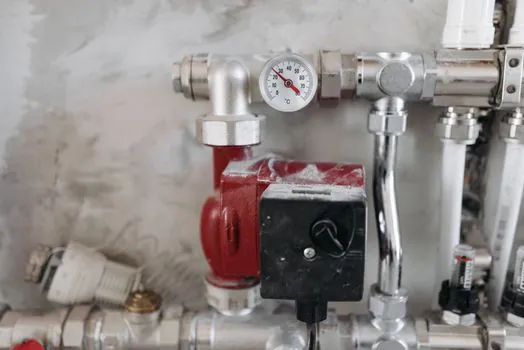
The four main manometer types map cleanly to duty. Bourdon-tube (C-tube, spiral, helical) covers roughly 0.6 bar to 1600 bar on gases, steam, and non-condensing liquids, and is the default for 80% of plant gauges. Diaphragm-seal manometers handle low range (0.16 bar to 40 bar) on viscous, slurry, or crystallising media where a Bourdon tube would clog. Capsule manometers read very low pressures (2.5 mbar to 600 mbar) on clean dry gases, including furnace draft and cleanroom differential. Differential manometers (two ports) read 0.16 bar to 25 bar differential across filters, strainers, and heat-exchanger coils, and tell you when to backwash or clean [S1].
Comparison on duty: a brass-bourdon dry-case 100 mm gauge at class 1.0, EN 837-1, G 1/2 B radial, is the cheapest unit (low single-digit to low-double-digit USD/EUR) and fits 70% of utility service. A 316L bourdon, glycerine-filled, 100 mm, NACE MR0175 (for H2S service where applicable), costs several times that. A diaphragm-seal gauge with Hastelloy wetted side runs roughly 5x to 15x the bare-gauge price. A 0.1% test-bench reference gauge is in a different category again. For an industrial valve upstream of a sensitive instrument, the diaphragm-seal gauge is normally the right spend; for a compressed-air drop leg, the brass bourdon is.
Who Should NOT Pick the Mainstream Option
Specifying a standard brass-bourdon dry gauge is wrong when: (a) the media is oxygen, acetylene, chlorine, or any oxidiser, because cleaning and material compatibility rule it out; (b) the service is pulsating (reciprocating compressor discharge, pump discharge near the check valve), where a liquid-fill or a snubber is mandatory or the bourdon fatigues in weeks; (c) the working pressure is below 0.6 bar, where a capsule or diaphragm gauge reads accurately while a Bourdon is non-linear near zero; (d) the media is a slurry, polymer melt, or scale-forming water, where a diaphragm-seal gauge with a flush or extended diaphragm is the only reliable choice [S1].
The same logic is why a PLC I/O card on a high-cycle pump station does not read a standard Bourdon through a 4-20 mA loop without a snubber or pulse-dampener upstream of the transducer; the gauge and the transmitter fail for the same mechanical reason. For pulsating service, either specify a liquid-filled gauge with a restrictor, or add a chemical seal / snubber in the line.
Standards Governing Manometer Specification

EN 837-1 covers Bourdon-tube pressure gauges for pressures above 0.6 bar. EN 837-2 covers selection and installation recommendations for pressure gauges with diaphragm seals. EN 837-3 covers capsule-type low-pressure gauges. ASME B40.100 is the North American equivalent, covering dial-type Bourdon gauges and defining accuracy classes 0.1% through 5%. For oxygen service, ASTM G93 / ISO 15001 define cleaning and contamination levels. For sour (H2S) service, NACE MR0175 / ISO 15156 restricts materials of construction. For hazardous-area gauges, ATEX 2014/34/EU and IECEx govern the certification of the instrument as a whole when the case is non-metallic or contains electronic components [S1].
For matched-skid builds, specifying all gauges to EN 837-1 with G 1/2 B connections, 100 mm dial, and class 1.0 simplifies spares and bracket design. For North-American plants, ASME B40.100 with 1/2 NPT is the equivalent baseline.
Shortlist Logic for a Spec
Step 1: lock the working pressure, temperature, and media. Step 2: pick the full-scale value at 1.5x to 4x the working pressure. Step 3: pick the wetted material from the media's chemical and temperature envelope. Step 4: pick the accuracy class (1.0% default, 0.25% or better for test bench). Step 5: pick the connection standard to match the piping. Step 6: add options (liquid fill, diaphragm seal, snubber, syphon, oxygen cleaning) only where the duty demands them. A gauge specified this way reads correctly for years; a gauge specified by price reads correctly for weeks. [S1]
Trackable signals: vendor datasheet revisions for compound-range vacuum/pressure gauges with EN 837-1 certification, and updates to ASME B40.100 annexes on gauge calibration intervals. For a related walk-through on a closely related duty, see the spec map for vacuum gauge selection criteria for water treatment skids and the pressure gauge buying guide 2026.