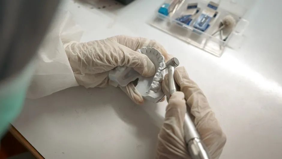
A standard injection mold base for a plastic part is sized first by the mold core envelope, then by gate family, slide count, and machine platen envelope, with stocked footprints running from 7.875 in. x 7.875 in. to 23.75 in. x 35.5 in. (200 mm x 200 mm to 603 mm x 902 mm) on the dominant A-Series 7-plate assembly [S3][S4].
The decision is structural, not cosmetic: form follows function (side gate, point gate, simplified point gate), then the base length dictates I, T, or H cross-section, and finally the plate stack, steel type, and ejection layout are matched to tonnage, projected area, and cycle life [S2][S5].
Standard footprints and plate stack-up you can actually order
The A-Series mold base is stocked in 43 sizes from 7 7/8 in. x 7 7/8 in. to 23 3/4 in. x 35 1/2 in. with 9 plate thicknesses from 7/8 in. to 5-7/8 in., making it the workhorse 7-plate assembly in North American mold shops [S3][S4]. DME publishes more than 75 trillion catalog configurations on the A-Series, with steel types coded No.1, No.3, and No.7 for cavity and core plate duties [S3]. For higher-temperature or corrosive resin programs, mold base is typically ordered in pre-finished P20 or H13 grades rather than the default AISI carbon steel, and that swap is usually specified through the catalog steel code rather than as a custom build [S3][S5].
The PCS Standard Aluminum mold base is offered in 9 frame sizes from 08/08 to 12/16 with A/B plate thicknesses from 1.94 in. to 3.44 in., giving prototype and short-run molders a lighter envelope for small parts where thermal cycling speed matters more than absolute tonnage capacity [S1]. Aluminum frames trade wear life for heat extraction, and that is a deliberate choice for F.I.T.S. (Fast Interchangeable Tooling System) quick-change cells, not a default for production [S1]. The B-Series 5-plate design folds the top clamp plate and A-plate into a single A-Clamping plate and eliminates the core-side support plate, keeping the same 7.875 in. x 7.875 in. to 23.75 in. x 35.5 in. envelope footprint for injection molding jobs that only need one parting line [S3].
Selection order: form first, size second, frame third
The form of the mold base is determined first, followed by the size, which depends mainly on the size of the mold core: the larger the mold core, the larger the mold base [S2]. Selection starts with the part's gate family, then slide and lifter count, then projected area on the parting surface, and only after those are locked does the catalog size get pulled. Side-gate bases suit simple one-step parting tools with permissive surface finish; point-gate bases are picked for single-cavity parts with large projection area, multi-cavity tools with internal feeding, gear or multi-cavity tire molds, and high-precision or long-life tools [S2].
Simplified point-gate bases (GAI/GCI series) are the right call when large slides or hydraulic cylinders on both sides of the cavity would otherwise stretch a full point-gate base to uneconomic lengths, or when a side-gate mold uses a cavity slide that has to clear the runner [S2]. A practical rule from the same source: when the overall base length is at or below 250 mm, use the I-shape; for 250-350 mm, use the T-shape; above 400 mm, pick the T-shape with a slide and the H-shape without a slide, and shift to a through-frame or H-shape whenever Plate A frame depth exceeds about 60 mm [S2]. For sand casting mold tooling the same form-first logic applies, though the plate stack is heavier and the steel choice moves to higher-chill grades.
Plate stack, steel codes, and ejection layout
A standard mold base includes a top clamp plate, A plate, B plate, C plate (spacer block), rear clamp plate, ejector pin plate, ejector retainer plate, guide pins, and return pins, and the spacer block height is set by the molded part's draw depth plus the ejection stroke [S5]. A 7-plate A-Series stack-up is Top Clamp Plate, A-Plate, B-Plate, Support Plate, Ejector Bar, Ejector Retainer Plate, and a 3-piece housing; the 5-plate B-Series folds the top clamp into the A-Clamping plate and drops the core-side support plate [S3]. Nine plate thicknesses from 7/8 in. to 5-7/8 in. cover most tonnage bands; special thicknesses outside that range are quoted as specials rather than pulled from stock [S3][S4].
Steel selection is coded, not negotiated: DME's A-Series and B-Series ship in No.1, No.3, and No.7 steel types, and the A-Plate typically forms the cavity or holds the cavity insert while the B-Plate holds the core insert or extends the runner [S3][S5]. A support plate is added on the lower mold whenever plate thickness alone cannot absorb the projected-area pressure at the planned clamp tonnage, which is also the trigger for stepping up to a heavier plate within the 7/8 in. to 5-7/8 in. thickness range [S3][S5]. The 3-piece ejector housing is fixed by the catalog; molders can omit, add, or relocate components, but the housing geometry does not change without a custom order [S3].
Who a standard base fits, and who needs a custom build
A standard A-Series or B-Series mold base fits roughly 80 to 90 percent of single-material injection jobs, specifically simple two-plate or three-plate tools, shot weights under about 1 kg, and clamp tonnage that stays inside a generic 50 to 500 ton press, because the catalog envelope (200 mm x 200 mm to 603 mm x 902 mm) covers the majority of small to mid-size part footprints [S3][S4]. Standard bases also fit side-gate and most point-gate layouts without modification, as long as the runner and gate bushing do not have to be relocated off-center to clear large cavities [S2]. Lead times are typically same-day or next-day for stocked assemblies from North American distributors, and that is the main commercial reason to standardize [S1].
Custom builds are required for large slide or lifter counts on both parting faces, circular mold cores that need a support plate, ejector housings that conflict with cavity guide pins, or any base that needs plate thicknesses outside the 7/8 in. to 5-7/8 in. stocked range, or footprints outside 7.875 in. x 7.875 in. to 23.75 in. x 35.5 in. [S2][S3]. A mold base with an ejector plate cannot be paired with a cavity guide pin and core guide bushing together; that combination is replaced by a longer guide pin (extended 10-15 mm into the slider) or a true custom build [S2]. For deep-cavity tools where Plate A frame depth exceeds about 60 mm, a through-frame or H-shape construction is also a custom-side decision, not a stock pull [S2]. Buyers who only need material handling or pulp-and-paper tooling should treat the same form-first logic as a starting reference, not a default; an in-depth mold base selection guide for pulp and paper walks through that adjacent case.
Selection criteria compared across the three gate families

Comparing the three gate families on the criteria that actually drive a buy: side-gate bases win on simplicity and cost for one-step parting tools with permissive surface finish, point-gate bases win on multi-cavity flexibility, internal feeding, and precision/long-life service, and simplified point-gate bases (GAI/GCI) win when large slides or cylinders on both sides of the cavity make a full point-gate base uneconomically long [S2]. On footprint, the A-Series and B-Series both stock 43 sizes in the 7 7/8 in. x 7 7/8 in. to 23 3/4 in. x 35 1/2 in. envelope, while the PCS Standard Aluminum line narrows that to 9 frame sizes (08/08 to 12/16) for the prototype and quick-change niche [S1][S3][S4]. On plate stack, A-Series is 7 plates with 9 thickness options from 7/8 in. to 5-7/8 in., B-Series is 5 plates in the same thickness range, and simplified point-gate GAI/GCI series share the 250 mm / 250-350 mm / 400 mm length thresholds that pick I-shape, T-shape, or H-shape frame cross-sections [S2][S3].
Two hard rules from the same selection reference keep the comparison grounded: the mold base with an ejector plate must not be paired with cavity guide pin and core guide bushing in core, and when the mold core is circular, use the base with a support plate [S2]. For high barrel or shell-shaped products, the point-gate family is the consistent recommendation regardless of frame size [S2].
Common sizing mistakes that scrap a mold base
The most expensive mistake is sizing the base to the part envelope instead of the mold core envelope, which under-runs the runner and gate bushing clearance and forces a custom build or, more often, scrapping the assembly [S2]. The second is picking the wrong gate family: forcing a point-gate base into a side-gate layout (or vice versa) typically shows up as off-center gate bushing, unbalanced fill in multi-cavity tools, or visible gate marks on cosmetic surfaces [S2]. The third is ignoring Plate A frame depth: a deep frame (above about 60 mm) in a stock I-shape base cracks under clamp load, and the fix is to step up to a through-frame or H-shape, not to thicken the B-Plate [S2].
A practical mistake-avoidance sequence from recent shop guidance: confirm the part's projection area on the parting surface first, then choose the gate family from that area, then check slide and lifter count against the frame length thresholds, then confirm the 7.875 in. to 23.75 in. envelope covers the cavity plus runner with at least 10-15 mm guide-pin engagement, and only then pull a catalog code [S6]. Aluminum frames in the 08/08 to 12/16 range are not a substitute for steel when the program exceeds a few thousand shots; they are a thermal and lead-time tool, not a wear-life tool [S1][S5]. Buyers building shortlists should also confirm the supplier's steel-code policy (No.1, No.3, No.7 on DME; equivalent P20/H13 coding elsewhere) before locking the order, because a steel swap is the single most common silent change between quote and delivery [S3][S5].
Sourcing signals to track through end of 2026

Three signals worth tracking through the rest of 2026: DME's online mold base configurator is under maintenance and temporarily unavailable, so any A-Series or B-Series quote requiring a non-stocked component is currently a manual special-order path rather than a self-serve build [S3]. PCS Company's Fraser, Michigan stocking of Standard Aluminum bases in 9 frame sizes is the lead-time benchmark for North American prototype and quick-change work, and same-day shipment on standard assemblies remains the published service level [S1]. For buyers looking at adjacent tooling decisions, a current spec-driven die casting die suppliers shortlist and a crossed roller guide selection check are the natural next nodes once the injection side is locked, because most multi-process cells re-use the same platen envelope and frame logic across linear guide and press-side slides.