
The ABB MNS-MCC Installation Manual is 44 pages long and includes sections on general information and system description, mechanical design, bus bar compartments, equipment compartments, wireways, and packaging and handling [S1].
This guide applies to low-voltage motor control centers containing motor starters, variable frequency drives, programmable controllers, and related control equipment [S2].
Define the MCC scope before installation begins
A motor control center is an assembly of one or more enclosed sections with a common power bus, primarily containing motor control units [S2]. A practical MCC installation follows project planning, preparation, execution, testing, commissioning, documentation, handover, and post-installation review [S2].
The electrical scope normally includes incoming feeders, horizontal and vertical bus bars, fixed or plug-in motor starters, breakers, contactors, relays, overload protection, control transformers, terminal blocks, and communication equipment. The common arrangement uses a horizontal main bus with vertical distribution from each section to individual motor-control units [S5].
North American procurement should specify UL 845 coverage for MCC construction, temperature rise, and short-circuit ratings [S5]. IEC 61439-2 is the comparable international framework for low-voltage switchgear assemblies and control devices [S5]. The approved drawings, one-line diagrams, nameplate schedule, component schedule, short-circuit rating, voltage, continuous-current rating, interrupting ratings, and cable-terminal sizes must be available before field work starts [S4].
This installation method fits grouped low-voltage motor loads, including pumps, fans, conveyors, compressors, and process machinery. It does not fit a single motor that can be served by a local disconnect and starter, nor does it replace individually engineered medium-voltage or high-voltage motor controls.
Review submittals and establish acceptance criteria
The MCC manufacturer should be the manufacturer of its major components, and the specified supplier should provide evidence of at least five years producing similar electrical equipment [S4]. The construction package must include final as-built drawings, unit wiring diagrams, certified production test reports, installation information, seismic certification, and equipment anchorage details [S4].
Before receiving equipment, convert the project drawings into inspection points. The ABB manual identifies separate sections for receiving, unloading, moving, section installation, shipping-split connections, horizontal-bus splicing, anchorage, cable connections, wiring, and commissioning [S1]. That sequence provides a defensible hold-point plan rather than treating installation and energization as one activity.
Set acceptance values before energization. Verify incoming phase sequence before applying power, then operate the main disconnect under the manufacturer procedure [S1]. Retain continuity and insulation-resistance test results in the commissioning file [S2]. Confirm that unit identification matches the nameplate schedule, starter schedule, wiring diagrams, and approved single-line diagram rather than relying on physical position alone [S4].
UL 845 applies to the North American MCC, while NEMA and ANSI standards may also govern design, manufacture, testing, and installation [S4]. NFPA 70 Section 90.1(B) treats its provisions as minimum installation requirements, while OSHA 1926 Subpart K, including Section 1926.403, addresses equipment suitability, examination, mechanical strength, insulation, heating, arcing effects, classification, and system installation [S2].
Receive, move, and position sections without damage
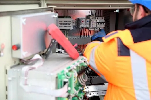
Inspect shipping sections before unloading because mechanical damage, missing hardware, and disturbed bus connections become harder to diagnose after the lineup is assembled. ABB provides dedicated instructions for packaging, receiving, unloading, moving MCC components, installation location requirements, section sequence, shipping-split connections, and fastening sections to floors, base frames, and walls [S1].
Use the manufacturer-approved lifting and handling provisions rather than pulling on enclosure doors, wiring, bus bars, or lifting eyes not intended for that load. Keep shipping supports installed until the required joints and anchorage are complete.
Position sections in the approved lineup and square the enclosure before tightening fasteners. Confirm floor level, wall clearance, access to cable entry and exit points, and the locations listed in the contract drawings [S4]. The project specification requires motor control centers and their components to be designed, manufactured, and tested in accordance with the latest applicable standards of NEMA, ANSI, and UL 845 [S4].
Do not force a shipping split closed, alter a cubicle height, or enlarge an enclosure field modification without the manufacturer's engineering instruction. ABB devotes separate procedures to cubicle-height changes, horizontal-bus splicing, and shipping-split connections, indicating that these operations can affect both mechanical fit and electrical continuity [S1].
Connect bus bars and field cables by torque-controlled procedure
Horizontal-bus splices and shipping-split connections are high-consequence joints because an inadequately torqued connection can heat under load, while a loose connection can produce arcing or an unreliable fault-current path. ABB separates bus-bar splicing from general installation and includes a 39-page section of assembly torque tables [S1]. Use the specified tool, fastener, pattern, and torque for the installed hardware rather than applying a generic torque value.
Wire power cables to the identified motor unit, control conductors to their designated terminals, and communication cables to their documented ports. Maintain segregation between power and control wiring where required by the approved design, and avoid loading terminal blocks with cable weight or unsupported strain. ABB includes a dedicated 13-section chapter on wireways and a cable-connections and wiring section [S1].
Field cable sizing, conductor type, terminal size, and entry method must match the approved documents. The submittal package requires cable-terminal sizes, product data sheets, busway connections, close-coupled assembly details, and a key-interlock scheme with its sequence of operations [S4]. For control-system interfaces, route compatible control cable separately from high-energy power conductors and terminate it at the documented terminal block or device.
After termination, compare conductor tags against unit wiring diagrams, tighten terminals to the manufacturer's specified values, and inspect for stray wire fragments, copper strands, damaged insulation, and tools left inside the enclosure. Do not energize a section merely because the incoming supply is present; the unit interlocks, covers, barriers, and grounding connections must be restored first.
Test feeders, motors, controls, and interlocks before energization
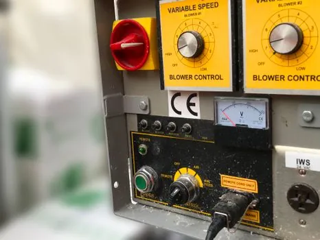
Commissioning should progress from static checks to energized tests, with each stage held until its acceptance criteria are met. The ABB manual begins with applying power at the main incoming, checking incoming phase sequence, switching on the main disconnect, and continuing through staged checks [S1].
Before energization, verify continuity, insulation resistance, grounding, bus connections, incoming phase sequence, outgoing motor-circuit identification, and mechanical operation of breakers, disconnect mechanisms, and withdrawable units. Check that the overload setting matches the protected motor data rather than a generic starter default. Functional testing should also prove remote-device operation, pilot indications, interlocks, trips, alarms, and communication links [S4].
For withdrawable units, verify the mechanical interlock before racking the unit into the connected position. The ABB manual includes troubleshooting for withdrawable-unit interlocks, unit insertion and removal, and inspection of operating mechanisms [S1]. If an interlock prevents movement, do not defeat or modify the mechanism to force the bucket into service; identify the open cover, shutter, handle, key, or auxiliary-contact condition that prevents movement.
The maintenance reference for related circuit breaker installation and commissioning can support the breaker-specific test checklist, but the MCC manufacturer’s drawings and procedure remain controlling documents. Record measured values, switch positions, trip results, and exceptions in the commissioning report rather than recording only a pass or fail notation [S2].
Energize each unit through a controlled sequence
Energize the MCC progressively: confirm incoming isolation and grounding, remove barriers or covers as required by the procedure, apply incoming power, verify phase sequence, close the main disconnect, and test one motor-control unit at a time before moving to the next load [S1]. This method limits the consequences of an incorrect feeder, phase, interlock, or control-circuit connection.
During testing, observe current, voltage, noise, heat, vibration, and starter response for each connected motor. Verify that the contactor pulls in, the overload remains normal, the motor runs in the required direction, and local or remote stop commands operate as designed. Correct any reversed rotation at the appropriate control or power interface under the approved isolation procedure; do not improvise by changing energized conductors.
Fixed units, plug-in units, and withdrawable units have different service constraints. ABB separates their operating instructions and provides specific procedures for removing and inserting withdrawable units [S1]. A unit must not be inserted, removed, or operated with the bus condition inconsistent with its position indicator and interlock sequence.
Replace the unit, escalate the issue, or quarantine the section if there is unexplained heating, damaged insulation, a failed interlock, incorrect bus phasing, inability to achieve the required test value, or repeated unexplained trips. These are not conditions to clear by repeatedly resetting equipment.
Close out documentation and establish maintenance controls
Final acceptance requires an exact match between field conditions and the handover file. The construction records must include final as-built drawings, unit wiring diagrams, certified production test reports, installation information, seismic certification, and anchorage details [S4]. The operating file should also contain the energization sequence, phase-sequence result, continuity and insulation-resistance results, unit trip settings, outstanding punch items, and approved operating procedures.
Train operators on the actual lineup rather than a generic MCC. The ABB manual covers operator handles, fixed and plug-in operation, withdrawable-unit service, lockout/tagout, inspection, and maintenance scheduling [S1]. Preserve access to the horizontal bus, vertical bus, wireways, terminal zones, unit interlocks, and arc-flash protection features shown in the approved layout.
Set a maintenance interval from the manufacturer's schedule and plant operating conditions. Inspect terminal tightness, unit condition, enclosure damage, heaters or fans where fitted, and the operation of protective devices. Replace damaged metal rather than leaving a cosmetic repair that compromises the enclosure, and escalate internal heating, damaged bus insulation, or recurring interlock faults [S1].
Track two handover signals: closure of every punch-list item with a verified test record, and confirmation that every operating and maintenance document matches the final unit configuration. Those controls preserve the installation's design intent through subsequent maintenance cycles [S2][S4].