
A motor protection relay isolates a faulty high-voltage induction motor during overload, locked-rotor, phase loss, or earth-fault events; a microcomputer-based protection relay performs the same trip functions but adds a programmable CPU core, digital metering, and serial/Ethernet communication [S4]. The two categories overlap on the basics — both are built around current transformers, contactors, and trip curves — but diverge sharply on integration depth, fault diagnostics, and price per I/O point.
Supply voltage ranges cluster around 65–265 VAC and 80–275 VDC for industrial-class units such as the Littelfuse MPU-32 and MPS series, with three Form-C (N.O./N.C.) or three Form-A plus two Form-C output contacts being the most common contact-budget pattern [S6]. Field wiring, panel cut-out, and trip-class selection, not digital features, are the usual hard constraints on the electromechanical side.
Scope: What Each Device Actually Is
A conventional motor protection relay is a discrete-component or solid-state protective device that samples motor current through CTs and compares it to a thermal model or fixed pickup; it trips an output contactor when the model is exceeded, with no user programming beyond dial-set trip class and current scale [S4]. A microcomputer-based protection relay — often called a numerical, digital, or microprocessor protection relay — replaces the analog trip engine with a microprocessor executing sampled-current algorithms, configurable protection elements, and digital I/O, typically supporting protocols such as Modbus RTU, DNP3, or IEC 61850 over RS-485 or Ethernet [S2].
For motor-only applications, the electromechanical or static relay still covers the four core protections (overload, phase loss, phase reversal, earth fault) in a 22.5 mm or 45 mm wide housing. For combined motor + transformer + line protection inside a substation below 35 kV, the microcomputer-integrated category marketed as “microcomputer integrated protection” explicitly bundles motors, transformers, capacitor banks, and PT/CT feeders under one CPU with RS-485 / CAN comms [S2].
Selection Criteria: Trip Class, Comms, I/O, and Environment
Trip class is the first hard gate. Class 5, 10, 20, and 30 trip curves are standard across both categories, and most motor protection relays expose a rotary selector for them; matching the relay’s trip class to the motor’s locked-rotor withstand time prevents nuisance trips on direct-on-line starts. Supply range matters on rural or battery-backed sites: the Littelfuse MPU-32 accepts 65–265 VAC or 80–275 VDC, which lets one part number cover both auxiliary feeds [S6]. Hazardous-area plants need a relay that is itself Ex-rated or installed outside Zone 1 — the Wilo CM-MSS.41S is explicitly Ex-rated for PTC/bimetal winding-temperature monitoring at 24–240 V AC/DC [S3].
On the microcomputer side, three additional criteria appear: communication protocol stack, event/fault record depth, and I/O expandability. A microprocessor protection relay with RS-485 Modbus can publish real-time current, voltage, and thermal capacity to a SCADA node; one with Ethernet can additionally publish waveform files for post-fault analysis. The SEL-710-5 illustrates the upper bound: it covers asynchronous and synchronous motors, adds broken-rotor-bar detection, and works with variable-frequency drive-fed motors where pure thermal overload relays are blind [S5].
For non-motor assets inside the same panel — capacitor banks, transformer feeders, overhead lines below 35 kV — the same microcomputer platform can absorb them, which is the single argument that pulls specifiers away from a dedicated motor protection relay toward a multi-function microcomputer protection device [S2].
Comparison Matrix: Conventional vs Microcomputer Protection Relay
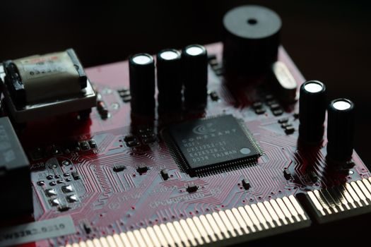
Specifying engineers should weigh four axes. (1) Cost per protected motor: a static thermal relay sits at the bottom of the bill of materials; a microcomputer relay can cost several times more but replaces an auxiliary relay cluster. (2) Protection depth: electromechanical and static units cover the four core faults, while microcomputer units add differential, restricted earth fault, broken rotor bar, and RTD/thermistor biasing [S5]. (3) Integration: static relays have hard-wired contacts; microcomputer units expose RS-485, CAN, or Ethernet and are programmable from a PC tool [S2]. (4) Diagnostics: static units provide a single trip LED; microcomputer units log trip reason, pre-fault current, and trip-time-to-fault for trending into a CMMS.
For a direct comparison: an ABB CM-MSx thermistor motor protection relay monitors PTC winding temperature for direct thermal protection of motors in hazardous areas [S1], while a microcomputer-based motor protection relay such as those sold under the “Intelligent Motor Protection Relay” category by Indian OEMs adds microcontroller-based logic, multi-parameter monitoring, and communication interfaces [S7]. The first is essentially a temperature-trip device; the second is a numerical relay with a CPU.
Who Each Type Is For — And Who It Is Not For
A conventional motor protection relay fits pumping, fan, and compressor panels where the trip logic is fixed, no SCADA integration is needed, and the user just wants overload + phase loss + phase reversal in one DIN-rail module. It is the wrong choice when the motor is VFD-fed, when broken-rotor-bar detection is required, or when a plant historian needs per-trip waveform data — those use cases are out of scope for an analog thermal curve. [S1]
A microcomputer protection relay is the right pick for substation-class motors above 1 MW, VFD-driven motors, synchronous motors with field excitation, and any plant rolling out a digital-twin or condition-monitoring layer. It is overkill for a 0.37 kW pump in a building-services panel; the install cost and the configuration effort will not be recovered. The SEL-710-5 datasheet is explicit that its broken-rotor-bar and VFD features exist for asynchronous and synchronous machines — applying it to fractional-horsepower DOL motors is wasted spend [S5].
For hazardous-area or explosive-atmosphere motors, the relay itself must carry an Ex rating or be mounted in a safe area; both the ABB CM-MSx family and the Wilo CM-MSS.41S are explicitly listed for hazardous-area winding-temperature monitoring [S1][S3]. Picking a non-Ex relay in that duty is a specification error, not a cost optimisation.
Real Use Cases and Sourcing Signals
Pumping stations in municipal water treatment remain the highest-volume buyer of discrete thermal motor protection relays, where the Wilo CM-MSS.41S is sold as an accessory that pairs PTC or bimetal sensors to trip a contactor on winding overtemperature [S3]. Hazardous-area conveyor motors in oil and gas take the ABB CM-MSx for the same reason: PTC sensors embedded in the winding feed a relay that does not depend on phase-current balance, which is the failure mode that defeats many electromechanical overload relays [S1]. Heavy-industry induction motors above 400 V use the SEL-710-5 or equivalent numerical relay so that broken-rotor-bar trending can be folded into a predictive-maintenance dashboard [S5].
For lower-tier industrial assemblies — MCC buckets, small pump panels, HVAC fan starters — Indian and Chinese OEMs sell micro-controller-based motor protection relays under the “Intelligent Motor Protection Relay” label, with multi-parameter monitoring and communication options at price points between a thermal relay and a full numerical relay [S7]. The Chinese relay-maker catalogue also lists a parallel “microcomputer integrated protection” line for substation feeders, motors, transformers, and capacitor banks below 35 kV with RS-485 and CAN interfaces [S2]. On the Littelfuse side, distributors such as BDTIC list the MPU-32 and MPS alongside a PGR-6100 ground-fault and insulation relay for panel builders who want a matched product family from one vendor [S6].
Limitations, Failure Modes, and Spec Pitfalls
Conventional thermal motor protection relays fail in three well-known ways: incorrect trip-class setting (the most common commissioning error), single-phasing that does not produce a measurable current imbalance on lightly loaded motors, and locked rotor after a voltage dip where the thermal model resets too aggressively. PTC-only devices such as the CM-MSx do not detect electrical faults at all; they only see winding temperature, so a short-circuit between turns can damage the motor before the PTC heats up [S1].
Microcomputer protection relays introduce their own failure modes: firmware version drift across a fleet, cybersecurity patching burden, and dependence on the auxiliary supply being within the declared range (typically 65–265 VAC / 80–275 VDC for industrial units) [S6]. A numerical relay that loses its auxiliary power during a fault cannot log the trip cause; the static relay beside it, with no CPU, will still open its output contact as long as the contactor coil is energised. Specifiers should therefore size the trip-class headroom and keep at least one electromechanical trip path in safety-critical circuits.
For sites that already run a safety relay chain for E-stops and guard doors, adding a microcomputer protection relay to the same panel is straightforward because the trip output is a standard Form-C contact that wires into the same safety logic. Standalone thermal relays pair just as easily with a thermal relay output to a contactor coil, which is why the electromechanical category persists in MCC designs.
Closing — three trackable signals for the next procurement cycle: confirm whether the motor is VFD-fed (selects numerical over static); confirm whether the panel must publish per-trip data to a plant historian (selects microcomputer over static); and confirm whether the motor sits in a classified hazardous area (forces an Ex-rated relay such as the CM-MSx or CM-MSS.41S) [S1][S3][S5].
See also our earlier report, Injection Molded Part Types and Industrial Applications: A 2026 Spec Map.