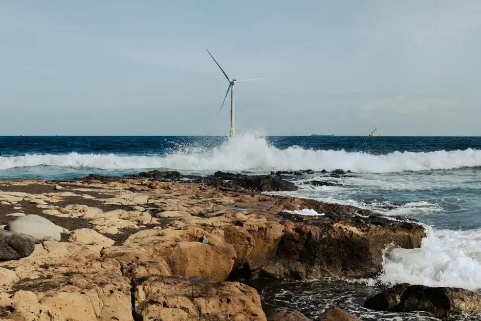
Offshore wind foundation process control and instrumentation spans pile-driving strain sensors, foundation SCADA, and continuous structural health monitoring (SHM) systems sized to support structures whose tower and foundation account for roughly one quarter to one third of the capital cost of an offshore wind farm [S2].
More than 80% of installed offshore wind capacity worldwide rests on monopile foundations, cylindrical steel piles driven into the seafloor, which makes impact-driving monitoring the highest-leverage instrumentation package in the segment [S1].
Foundation Architecture Drives the Instrument Choice
Monopiles used in offshore wind can exceed 30 feet (roughly 9 m) in diameter and experience large driving stresses that consume a significant portion of the structure's fatigue design life, which is why strain-gauge and accelerometer arrays are now standard on the hammer leader [S2][S9].
Jacket foundations, four-leg lattice structures borrowed from oil and gas, are gaining share as turbines scale to 9-9.5 MW with rotor diameters over 500 feet, because the lattice uses less steel per MW than a comparably loaded monopile, but they require distributed node-level instrumentation on every tubular joint [S1]. Suction-bucket hybrids such as the Mono Bucket add a separate load-monitoring need at the bucket-seabed interface, where underpressure installation must be recorded against pore-pressure response in soft clays [S1].
What Has to Be Measured: The Four-Channel Baseline
A working offshore wind foundation instrument package covers four channels: (1) natural frequency of the as-built tower-foundation system, because resonant amplification drove the 1940 Tacoma Narrows failure and design estimates are not reliable enough to leave unverified [S2]; (2) pile-driving strain and acceleration during installation, to back-calculate fatigue consumed and detect over- or under-design relative to the soil actually encountered [S2][S9]; (3) long-term fatigue and extreme-load response from wind, wave, rotor, and 1P/3P blade-passing excitation, used to track whether U.S. East Coast hurricane loading is outpacing the historical statistical basis in the design codes [S2]; and (4) scour and seabed-elevation change around the foundation base, normally via multibeam sonar surveys or buried transducers.
The control system then ties these into a foundation-level SCADA stream that runs in parallel with the turbine-level SCADA. Siemens Energy markets the Omnivise T3000 platform with a dedicated foundation SCADA layer alongside the wind park controller, illustrating how this function is now treated as a distinct subsystem rather than a sub-channel of the turbine PLC [S6].
Selection Criteria: Match the Sensor to the Failure Mode
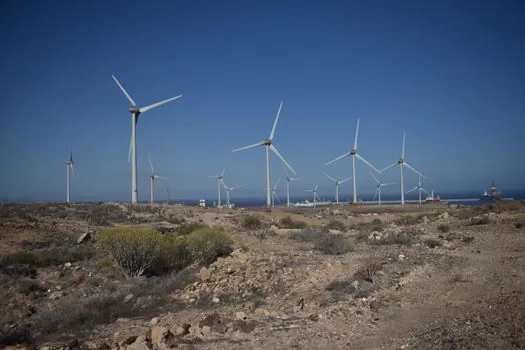
Three criteria separate a defensible instrument package from a checkbox installation: relevance to the governing failure mode, survivability in the marine environment, and recoverability of the data. [S2]
On relevance, monopile impact driving is governed by axial strain and hammer-blow energy transfer, so optical-fiber Bragg grating (FBG) strain chains and accelerometers mounted on the pile wall during fabrication have become the default; alternatives such as surface-mounted foil gauges suffer from drift and bond degradation under high-cycle hammer loading [S9]. For jacket nodes, the failure mode shifts to multi-axial fatigue at welded tubular joints, which favors multi-axis strain rosettes welded to the joint chord.
On survivability, sensors must operate in saltwater splash zones, sustain hydrostatic pressure at the seabed interface, and resist marine growth. IP68-rated or submarine-cable-junction (SCJ) housings with polyurethane-jacketed armoured cable are the typical baseline; copper-cable signal integrity over the 50-100 km subsea run back to the offshore substation is the real bandwidth bottleneck and usually forces a serial or fiber-mux architecture rather than analog 4-20 mA loops per sensor. Comparisons across the four main foundation options on these criteria line up as follows:
- Monopile: lowest sensor count per foundation, highest per-sensor value; driving strains are the dominant signal; jacket penetration of the cable through the transition piece is a recurring leak path that has to be designed out.
- Jacket: highest sensor count per foundation because every welded joint is a candidate; node-level rosettes dominate; cable management is more complex but the platform is accessible from the boat landing.
- Suction bucket / Mono Bucket: adds pore-pressure transducers in the surrounding soil; lower driving loads but unique installation underpressure signature that must be recorded as a one-shot event.
- Floating foundation (spar, semi-submersible, TLP): shifts the load problem to mooring-line tension and platform motion, so the instrument baseline is closer to an oil-and-gas FPSO than to a fixed-bottom wind turbine.
Who This Is For, and Where It Stops Paying Off
Foundation-level structural monitoring pays back on utility-scale offshore wind farms of 50 MW and larger, where the support structure is the single largest balance-of-plant cost line and where insurer and lender due-diligence increasingly asks for as-built performance data; smaller demonstration arrays under 30 MW typically cannot amortize the SCADA integration, cable landing, and 20-year data-hosting cost [S2][S5].
It is not a sensible scope for land-based or nearshore fixed turbines on conventional spread-footing foundations, where the dominant loads are static and the fatigue budget is not the binding constraint. A standard substation-grade process control cabinet can host the foundation SCADA, but it should not be confused with a turbine-controller cabinet: the sampling rates, time synchronization, and data retention policies are different, and the foundation stream has to survive independently of any turbine-level outage.
Process Calibration, Driving Monitoring, and the Pile-Soil Loop
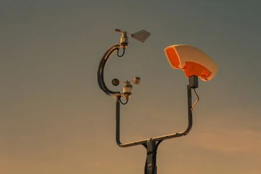
Pile-driving monitoring is functionally a process calibration exercise: the hammer energy, ram stroke, and blow count measured at the leader are correlated back to the Soil Resistance to Driving (SRD) and the as-built soil profile, and the resulting capacity curve is then compared to the design drivability study [S9]. Where the field curve diverges from the prediction, the foundation may be over- or under-designed for the lifetime fatigue loading it will actually carry, which is the one finding that justifies the cost of the entire instrument package on a monopile project [S2].
Modern impact-driven monopile installations rely on the IHC S-1500 / S-2000 / S-3500 class hydraulic hammers and similar large-rig hammers, with leaders that already carry an instrumentation backbone for blow-count, ram-stroke, and hammer-energy telemetry; the foundation-side add-on is the strain and acceleration chain on the pile itself, which has to be installed at the fabrication yard before the pile is loaded out [S9]. The typical foundation vehicle handling these piles is a jack-up or heavy-lift vessel, and the structural sensor package has to be compatible with the upending and lift rigging without creating snag points.
Standards, Sourcing, and Federal Context
Offshore wind developers in the U.S. work against a process book that has not changed substantively: a Bureau of Ocean Energy Management (BOEM) lease, a Site Assessment Plan, a Construction and Operations Plan, and the construction machinery and equipment mobilized to execute the pile-driving and jacket-lift campaigns [S5]. Since January 2025, the federal government has stopped planning for and approving new offshore wind projects, but the process and standards framework described here remains the reference for the existing pipeline and for any restart of federal permitting [S5].
Design-side standards commonly invoked for foundation instrumentation include IEC 61400-1 for design loads, DNV-OS-J101 for offshore wind turbine support structures, and API RP 2A-WSD for the oil-and-gas heritage of jacket design; the 2023 Block Island monitoring paper (Hines et al., 54 citations) gives one of the few published field datasets for a fully instrumented U.S. jacket foundation and is the cleanest reference for sensor selection on a Gulf-style jacket [S3]. On the controls side, IEC 62443 is the reference for cybersecurity zoning between foundation SCADA, turbine SCADA, and the park-level controller, and the Omnivise T3000 architecture is one example of how that zoning is implemented in product [S6].
Limits, Failure Modes, and Open Questions
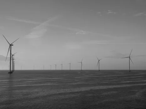
The dominant failure mode for foundation instrumentation is not sensor failure at the sensor itself, it is the subsea cable and the transition-piece penetrations; wet-mate connectors and J-tube routing have driven more monitoring outages on operating farms than sensor drift has. A second constraint is data bandwidth: a 50-100 turbine farm streaming 200 Hz strain and acceleration from every joint is well beyond what a standard offshore wind SCADA link was sized for, and the realistic answer is edge processing at the foundation with event-based uploads rather than continuous raw streaming. Third, the lamps and light fittings on the foundation platform and boat landing have to be specified for the same marine corrosion class as the structure, which is why Ex-de or IP66 marine-grade LED fittings with bronze or stainless hardware tend to be reused across both the foundation and the offshore substation. The 2025 dynamics review (Xie et al., 9 citations) flags pile-soil interaction under seismic and combined wave loading as the area where the existing field data is thinnest, which is the most plausible justification for the next generation of dense, multi-axis instrumentation campaigns [S8].
Track the next Block-Island-style published monitoring dataset, any IEC 61400-1 or DNV-OS-J101 revision covering SHM requirements, and the first foundation-instrumentation package tender on a U.S. project of 1 GW or larger, those are the signals that will tell the market whether the foundation SCADA layer is consolidating into a standard bill of material or staying project-engineered.
Background reading: Digital Panel Meter Suppliers 2026: Brand Map, Spec Cutouts, and Sourcing Logic.