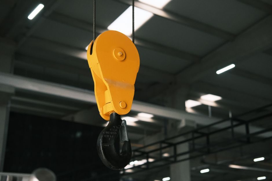
Overhead bridge crane selection is governed by four hard gates — Safe Working Load (SWL), span/lift height, duty service class per FEM 1Am–5m / ISO 4301, and girder configuration (single vs double, top-running vs under-running) — and buyers who reverse that order consistently over-spec the hoist, the runway, or both [S1][S2].
Top-running double-girder units dominate the heavy end (typical builds 5 t to 500 t, spans to 31.5 m, lift heights to 60 m in OEM catalogue offerings), while single-girder top-running and under-running (under-hung) units cover the 1 t–20 t mainstream, including overhead bridge crane selection gates buyers commonly misjudge [S5].
Define SWL, Hook Geometry and Service Duty Before Anything Else
SWL is the maximum static load the crane is rated to lift, including the weight of the lifting accessory (hook block, below-the-hook lifting beam, magnet, or C-hook) — the rigging weight is added to the payload, not assumed to be negligible [S1]. Duty service is then expressed against FEM groups 1Bm/1Am (light, occasional maintenance) through 4m/5m (heavy, near-continuous, hot-metal or scrap-yard duty) or the equivalent ISO 4301 classification, and the hoist gearbox, motor sizing and brake class are pulled from that rating, not from SWL alone [S2][S5].
Hook approach dimensions (headroom above the hook, hook-side clearances for sling angle, distance between hook centres on a twin-hook unit) define the building hook height and the lift envelope. A European-design LH double-girder in OEM catalogue data covers spans from 6 m to 31.5 m, lift heights from 3 m to 60 m, and a working-temperature window of −25 °C to +40 °C, which is the typical envelope procurement should validate before floor plan freezes [S5].
Span, Runway Rails and Building Interface
Span is the centre-to-centre distance between runway rails and must be matched to the building column grid, not rounded for convenience — a 19.5 m bay with a 20 m crane adds 250 mm of cantilever per side and shifts wheel reactions outboard. Top-running cranes transfer load through rail wheels onto a runway beam (typically S275/S355 fabricated I-section or a vendor-supplied box-section rail girder), while under-running units hang the end carriage on the bottom flange of the runway, which removes the building column vertical load but adds deflection limits on the runway itself [S1][S2].
Wheel load and reaction per wheel should be back-calculated for the worst case (SWL plus trolley plus bridge self-weight at the corner where the trolley is closest to the end carriage) and then compared to runway beam capacity plus rail-clip allowable. Single-girder under-hung cranes are typically limited to lighter SWLs because the runway beam carries crane + load in bending; once SWL passes roughly 10 t, most specifiers move to top-running single-girder or double-girder to keep runway steel within reasonable depths [S1][S2].
Single-Girder vs Double-Girder: Cost, Headroom and Hook Path

Single-girder cranes run the hoist on a trolley beneath the girder, which saves building height and reduces bridge self-weight — the typical sweet spot is 1 t–20 t, spans to ~25 m, with low-headroom and standard-headroom trolley variants. Double-girder cranes run the hoist on rails on top of the two girders, so the hook travels between the girders and can sit closer to the building column line; this is the configuration used for heavier SWLs, longer spans, and any application needing a maintenance platform on the crane [S1][S5].
Selection rule of thumb used by integrators: pick single-girder for low-headroom, lighter-duty work where capital cost dominates; pick double-girder for SWL above the 20 t mark, span above 25 m, heavy duty class, or where the end user wants a crab-style hoist service walkway. The decision flows directly into girder fabrication cost — a 10 t double-girder European-design unit in OEM data is a real catalogue configuration, with low-headroom and standard-headroom trolley options that change the hook approach dimension and the building hook-height requirement [S5].
Hoist, Travel Drives and Control: VFD, Anti-Sway and Pendant vs Radio
Hoist choice is normally between wire-rope electric hoists (the default for most industrial duty) and chain hoists (light service, clean, infrequent lifts). Travel drives use squirrel-cage or VFD-controlled motors, and on duty classes 3m and above, VFD acceleration/deceleration ramps are now standard to limit load swing and reduce in-service wear of ropes, sheaves and brakes [S2][S4].
Anti-sway control is an active engineering area — gain-scheduling approaches that adapt damping to payload mass and rope length have been demonstrated on overhead bridge crane test rigs to reduce residual oscillation after positioning, which directly shortens cycle time and improves operator safety on the linear guide that the trolley rides on [S4]. Control hardware typically includes pendant pushbutton as baseline, radio remote as the next step, and cab-operated for heavy-duty or large-span cranes where the operator needs line-of-sight to the load across a 30 m+ bay [S2].
Power Delivery, Electrification and Conductor Bar Selection
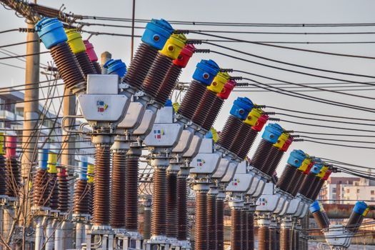
Power to the moving crane is normally delivered by a festoon system (cable loop on rollers) for light/medium duty, or by a rigid conductor bar (e.g. insulated copper or steel bar with sliding collector) for heavy duty and high-cycle service. Conductor bar ampacity must be sized for the sum of hoist, bridge travel and trolley travel simultaneous loads with a defined duty cycle; undersized bar is one of the top commissioning punch-list items on new bridge crane installations [S1][S2].
For under-running (under-hung) cranes the electrification often shares the runway I-beam flange geometry, and a related decision is whether to integrate a monorail overhead conveyor branch off the same runway for workstation delivery — common in automotive and paint-shop layouts. For cleanroom and pharma halls, a sealed conductor system, stainless trim, and low-particulation hoist are specified to control particulate generation, which is covered in the pharmaceutical overhead bridge crane spec-first selection guide [S2].
Safety Devices, Standards and Site Verification
Bridge crane installations in North America are typically designed against CMAA 70/74 duty classifications, while European builds follow FEM 9.341 / ISO 4301 and are CE-marked under the Machinery Directive [S2].
Verification on site is a real gate: dimensional check of span and runway alignment, rail joint smoothness, gauge and cross-level of rails, dynamic load test at 1.25 × SWL, and static load test at 1.5 × SWL (or per the governing standard) before handover. Field casework on heavy-lift bridge widening projects — such as the I-481 widening over the CSX rail yard in Syracuse, where gantry-style bridge cranes were used to solve access constraints — illustrates how specifying a crawler crane or gantry for the site-lift phase has to be coordinated with the permanent building crane envelope before steel goes up [S3].
Where Sizing Goes Wrong: Five Recurring Failure Modes

Five patterns dominate spec miscalls: (1) SWL chosen from the heaviest single load with no duty-class thought, which under-frames the hoist; (2) span read from inside-of-column instead of centre-of-rail, which shortens the runway by 200–400 mm and forces rail clip rework; (3) hook height chosen for nominal lift without checking building hook height minus trolley approach dimension, which traps the crane under a low bay; (4) duty class under-rated for the actual cycle count, which burns brakes and ropes; (5) runway beam deflection ignored, which on under-hung cranes shows up as trolley hunting and accelerated wheel-bearing wear [S1][S2][S4].
The crossed roller guide on the trolley and the crane scale hung below the hook are the two retrofit instruments that surface problems 3 and 4 in service — a crane scale gives the operator a real-time load readout that the overload limiter can be calibrated against, and the crossed-roller trolley guide is the mechanical element that determines positioning repeatability and is sensitive to runway alignment [S4].
Trackable next signals: confirm runway rail alignment and weld smoothness at handover against the alignment tolerance in the spec (commonly ±1–2 mm across the span), record no-load and full-load current draw on hoist and travels to baseline motor health, and verify conductor bar temperature rise at rated duty cycle before signing off on a 12-month warranty start — these are the items that separate a properly sized overhead bridge crane from one that fails the first quarter in service [S1][S2][S4].