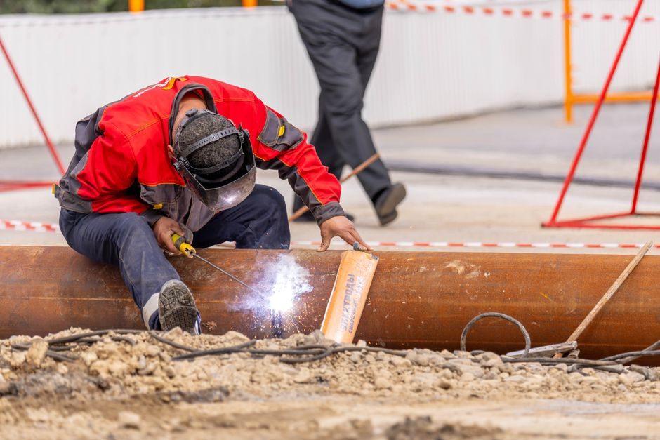
A correctly installed plasma cutter is not about plugging in and striking an arc — it is four independent physical interfaces that must all pass acceptance before the pilot arc fires [S1][S8].
Handheld and mechanized units from Hypertherm's Powermax family span 15 A (Powermax30 AIR, 8–16 mm severance) through 125 A (Powermax125, thick-plate gouging) on different mains and air envelopes [S1][S4][S6]. A clean install maps each gate to a measured value, not to a checklist guess [S8][S9].
Gate 1 — Mains Power, Breaker Sizing, and Duty Cycle
Plasma cutters draw 1.5–3× their nominal kW at arc strike because of the pilot-arc inrush, so the supply breaker must be sized to the nameplate's "slow-blow" or "D-curve" recommendation, not the running kVA [S1]. The Carmon model 450 entry on the market data lists 230 V ±10 %, 50/60 Hz, 270 V OCV, and 2.4 kW nominal at 100 % plasma output with a 35 A / 50 % duty cycle, which is a textbook single-phase 16 A plug envelope [S1]. Hypertherm's Powermax30 AIR runs on 120/240 V single-phase and explicitly markets itself as the smallest handheld air plasma in the line, so undersizing its branch circuit is the most common shop fault [S1]. For a mechanized 400 A-class inverter like the 1215-series CNC plasma table, three-phase 380–400 V with a dedicated breaker and a line reactor is mandatory to keep the IGBT stack inside its thermal window [S1].
The 50 % duty cycle at 35 A quoted on the Carmon 450 means the torch can cut for 5 minutes out of every 10 at that current; pushing past it trips the thermostat and aborts the cut, which on a CNC table is interpreted as a lost program step [S1]. Hypertherm's Powermax105 SYNC is rated 1-1/4 in (≈32 mm) handheld severance and 5/8 in (≈16 mm) mechanized severance on mild steel, a ratio that itself reflects the duty-cycle derating between handheld and table use [S6]. Read the back-panel label, not the marketing brochure, before you commit to a breaker size [S1][S8].
Gate 2 — Compressed-Air Supply, Filtration, and Pressure Setpoint
Air plasma machines need clean, dry, oil-free compressed air at a specific flow and pressure — typically 5–8 bar (≈70–115 psi) at 100–300 L/min depending on the model's current rating [S1][S4]. The Powermax30 AIR has an internal compressor for portability, but every other Powermax and every entry from TECHNOLIT, NI CNC, and Carmon in the 2026 industrial catalogue requires an external airline [S1][S4]. Abrasive dust and condensate in the supply line contaminate the consumable stack and erode the nozzle orifice within minutes, which is why Hypertherm ships a consumable-installation video that always starts with an airline purge before seating any cartridge [S8].
Air pressure must be set with the air flowing through the torch (post-purge) using the machine's regulator, not the compressor's wall gauge, because regulator-to-torch pressure drop on long hoses routinely runs 0.3–0.5 bar [S8]. For CNC table work driven by LinuxCNC's QtPlasmaC, the plasmac component monitors arc voltage to enforce a THC (torch height control) setpoint, and unstable air pressure shows up as a wandering arc voltage before it shows up as a poor cut [S9]. For comparison, handheld plasma cutter work tolerates a wider pressure band than mechanized cuts because the operator visually compensates; CNC cutting does not [S9].
Gate 3 — Torch Body, Consumable Stack, and Cartridge Orientation
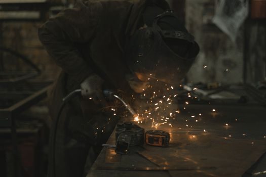
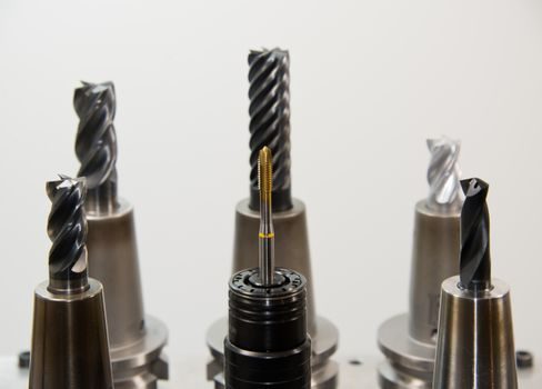
Hypertherm's consumable-installation video is the single most-watched reference for a reason: every Powermax torch family (Duramax, FineCut, HyDefinition) uses the same four-piece stack — shield, nozzle, electrode, swirl ring — but the orientation of the swirl ring and the torque on the electrode differ between handheld and mechanized cartridges [S8]. The FineCut cartridge on the Powermax105 SYNC cuts 1/8 in (≈3 mm) mild steel with a markedly different standoff than the standard 1-1/4 in severance cartridge, and swapping one for the other without re-checking the cartridge data plate is the leading cause of "no arc" or "arc but no cut" on commissioning day [S6][S8].
Mechanized CNC cutting uses a different shield than handheld work; the mechanized shield is a simple sleeve, while handheld work uses a drag shield with standoff feet that physically contact the plate [S8]. A drag shield on a CNC torch will crash into the plate when THC tries to maintain arc-voltage height — a classic field failure that is resolved only by re-stacking, not by re-calibrating the table [S8][S9]. For a rebar cutter workflow running handheld, by contrast, the drag shield is correct and an unshielded mechanized cartridge will give poor squareness on the cut face. Match the consumable to the application, then verify with the cartridge's own colour-code ring [S8].
Gate 4 — Work Clamp, Grounding Path, and Plate Preparation
The work clamp (also called the ground lead) must make a clean metal-to-metal contact on the workpiece or the cutting table, not on paint, rust, scale, or a painted fixture [S1][S8]. A high-frequency start plasma unit — like the ARCBRO 60B-class CNC cutter in the industrial catalogue — generates significant EMI, and the work clamp is the return path for the cutting current; a poor clamp forces current to seek alternative paths, which on a CNC table will feed back into the THC, the ohmic contact, or the controller's analog ground [S1][S9].
Clamp placement matters: the clamp should be as close to the cut line as practical, on the same piece of metal being cut, never on a separate fixture plate that is only loosely bolted to the workpiece [S1]. For a marble cutter or concrete groove cutter workflow this is irrelevant, but for plasma the clamp-to-arc distance should be under 0.5 m wherever geometry allows, because every metre of return path adds resistance and reduces effective cut power [S1][S8]. The LinuxCNC plasmac component's arc-OK interlock reads the contactor state, and a poor clamp will produce intermittent arc-OK dropouts that stop the table mid-cut [S9].
Side-by-Side: Handheld vs Mechanized (CNC) Plasma Installation
The two installation profiles diverge on every gate, not just on the consumable stack [S1][S6][S8][S9]:
Handheld (Powermax30 AIR, Powermax105 SYNC handheld mode): single-phase 120/240 V on a 16–30 A breaker; portable compressor or shop air 5–8 bar; drag shield; work clamp within 0.5 m; operator-controlled standoff ≈ 2–4 mm; severance up to 32 mm on mild steel with the 105 SYNC [S1][S6].
Mechanized CNC (ARCBRO 60B, 1215-series, QtPlasmaC-driven tables): three-phase 380–400 V on a dedicated breaker with line reactor; shop air with regulator, dryer, and pre-filter; mechanized shield (no drag); THC setpoint typically 100–120 V arc voltage for mild steel; controller interlocks on arc-OK, ohmic contact, and float-switch; severance up to 25 mm at 60 A and up to 35–50 mm at 400 A [S1][S9].
The decision rule: handheld installation is forgiving on the air and grounding gates because the operator compensates; mechanized installation is unforgiving on every gate because the controller samples them in real time [S8][S9].
Acceptance Test and First-Cut Verification
Before signing off the install, run a three-step acceptance test: (1) open the air regulator with the torch unplugged, confirm 5–8 bar at the torch inlet and zero condensate in the drip leg; (2) clamp to a clean mild-steel coupon, set current to the cartridge's nameplate, and verify pilot-arc strike within 1 second at the recommended standoff; (3) on mechanized cuts, command a 100 mm square in the controller and read the arc-voltage trace for steady-state within ±2 V of the THC setpoint [S1][S8][S9]. Hypertherm's consumable video frames this as "purge, stack, strike, square" — a useful field shorthand [S8].
Do not skip the first-cut coupon; a 3 mm mild-steel square at 30 A is the cheapest way to surface a marginal ground, a tired consumable, or an air-starved torch before the production job starts [S6][S8]. When this level of motion and current coordination is the job, an industrial surveillance camera install spec is irrelevant, but the same logic — gate-by-gate acceptance with a measured value at each step — does apply.
When NOT to Field-Repair — Escalation Triggers
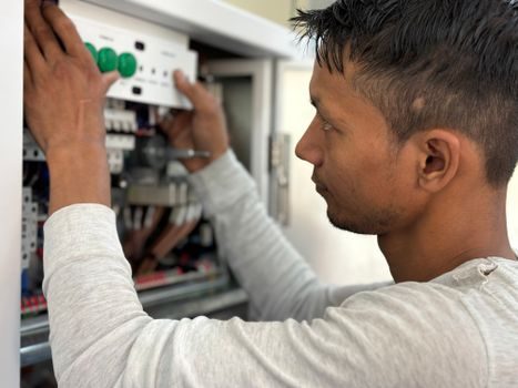
Escalate to the manufacturer's service channel rather than field-repair when: the IGBT or contactor fails the dielectric-withstand test (500 VDC megger); the torch body shows cracked insulation at the strain relief; the air regulator will not hold setpoint within 0.2 bar; or the consumable cartridge data-plate is unreadable [S1][S8]. For workflow questions that involve other machines in the shop, see the selection map for a TIG welding machine before adding a second heat-source to the same cell. A torch swap or consumable re-stack is field-repairable; a control-board replacement is not, and the installer's job ends at the gate of the cabinet [S8].