A TELWIN TECHNOLOGY TIG 230 DC + ACC draws 4,100 W from a 230V single-phase mains and is programmable down from 20A to 16A fuse input [S1]. A SUPERIOR TIG 422 WAVE AC/DC AQUA pulls 12,900 W (230V single-phase) or 17,300 W (400V three-phase) and ships with a trolley, TFT screen, and USB data logging [S3]. Before the TIG torch is ever fired, the installation must be a reproducible workflow, not a "plug and pray" exercise.
For a process engineer taking delivery, the 4 mandatory installation phases are: (1) electrical siting and mains verification, (2) protective-device and grounding check including the VRD device, (3) gas/coolant circuit preparation, and (4) controller parameter set-up using EASY or PRO mode. The reference frame for general TIG theory and process selection is laid out in the TIG welding reference guide and the related arc welding process trade-offs article.
Phase 1 — Site, Mains, and Nameplate Verification
Single-phase 230V @ 50/60 Hz and three-phase 400V @ 50/60 Hz are the two mains configurations found across the current Telwin manual-TIG family [S1][S3][S4][S5][S6]. The TECHNOLOGY TIG 230 DC + ACC is single-phase only and can be programmed to draw through a 16A fuse instead of 20A, a useful field trick for sites with low-amperage wall outlets [S1]. Cross-check that nameplate voltage, frequency, and absorbed power (e.g. 8,000 W on the SUPERIOR TIG 421 DC + ACC at 400V three-phase [S6], 17,300 W on the SUPERIOR TIG 422 WAVE AC/DC AQUA at 400V three-phase [S3]) match the feeder rating before energising.
Mount the unit on the trolley, bench, or floor stand rated for its mass; the SUPERIOR TIG 422 WAVE AC/DC AQUA is supplied on a dedicated trolley to keep the cooling air tunnel clear of dust ingress [S3]. A MIG-O-MAT longitudinal welding machine running plasma keyhole welding draws 350A at 100% duty cycle and is prepared for integration into a plant energy-management system, illustrating that a higher-tier TIG installation is a power-distribution project, not just a wall outlet [S2].
Phase 2 — Grounding, Fuse Sizing, and the VRD Device
Grounding is the single installation step that defeats the largest number of warranty claims and accident reports. The TECHNOLOGY TIG 230 DC + ACC carries a built-in VRD (Voltage Reduction Device) explicitly for greater operator safety in damp environments, alongside anti-stick, thermostatic, over-voltage, under-voltage, and over-current protection [S1]. The 16A-versus-20A fuse programming on the same machine is the practical lever for older buildings where the panel cannot deliver a 20A branch circuit [S1].
A second machine, the SUPERIOR TIG 422 WAVE AC/DC AQUA, is also VRD-equipped and adds a remote-control connector and a sealed dedicated-tunnel cooling path that physically separates electronics from shop-floor dust [S3]. For three-phase 400V cabinets like the ELECTROMIG 550 SYNERGIC (11,000 W on 230V single-phase / 15,000 W on 400V three-phase [S5]) and the MASTERMIG 305i (5,800 W / 7,500 W [S4]), the dedicated neutral and protective-earth conductor sizes must follow the cabinet-rated absorbed power, not the legacy outlet.
Phase 3 — Gas, Coolant, and Torch Circuit Preparation
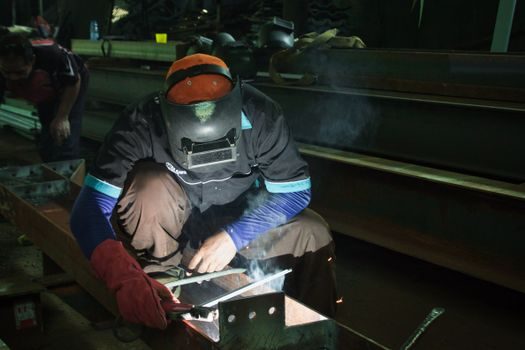
Argon shielding circuit integrity is checked before the HF strike. TIG uses an inert gas shield around a non-consumable tungsten electrode, with the gas envelope protecting both the tungsten tip and the weld pool from atmospheric contamination [S7]. A leak at any quick-connect on the gas hose silently starves the arc; on the SUPERIOR TIG 422 WAVE AC/DC AQUA, the "AQUA" suffix denotes an integrated water-cooling loop for the torch, and that loop is bled and pressure-tested before first arc [S3].
Pre-flow (gas-before-arc) and post-flow (gas-after-arc) timers are field-tunable on the TECHNOLOGY TIG 230 DC + ACC and are part of its microprocessor-controlled TIG regulation set [S1]. Typical field values for these timers fall in the 0.3–1.0 s pre-flow and 3–10 s post-flow window for mild steel and stainless; outside that envelope, tungsten oxidation at arc start (pre-flow too short) or wasted argon and soot at cup exit (post-flow too long) are the usual symptoms. Reverse that logic before drawing a torch swap, because post-flow is the parameter most often set by feel.
Phase 4 — EASY vs PRO Parameter Set-Up and Acceptance Test
The current Telwin higher-end manual platform (WAVE OS) forces a deliberate choice between two user modes: EASY mode (input material + thickness, the controller sets the rest) and PRO mode (full custom access to all individual parameters) [S3]. Acceptance on EASY mode is binary — input 2 mm stainless and the controller should land within its own recommended envelope without operator intervention. Acceptance on PRO mode requires a documented witness coupon: a 2 mm stainless test piece, a full-penetration TIG bead, and an end-of-weld crater-fill current down-slope that visibly closes the crater.
Set-up tasks that look minor but fail acceptance: forgetting the "bi-level" foot-pedal current, skipping current up/down slope, ignoring square-wave frequency on AC aluminium welding, and leaving balance DC-AC at the factory default [S1][S3]. The EASY PULSE / THINSPOT functions on the TECHNOLOGY TIG 230 DC + ACC and the SUPERIOR TIG 422 WAVE AC/DC AQUA are the factory defaults for thin-sheet work and reduce thermal distortion, but they are not a substitute for proper fixturing [S1][S3]. For workshop-rough context, broad shopping references like Amazon's TIG best-sellers and a TIG/MIG retailer front page [S8][S10] track what accessories (tungsten electrodes WT20/WETh-2 in 3/32" x 7", ER308L filler 1/16" x 16") are actually being bought at the install site. Related step-by-step electrical work on arc-welding power, grounding, and duty-cycle sizing is covered in arc welding machine installation: power, grounding, and duty-cycle specs.
Phase 5 — Failure Modes, Limits, and When NOT to Repair

Three installation-time failure modes dominate warranty tickets: (1) HF/LIFT strike mis-configuration (LIFT start is mandatory in electrically noisy or wet environments, HF start is the default for clean dry shops) [S1]; (2) thermal trip from blocked air-tunnel inlets, especially on trolley-mounted WAVE units — the tunnel is a deliberate dust barrier and must not be obstructed [S3]; (3) machine capability outside the workpiece class, for example, trying to run AC aluminium on a DC-only TECHNOLOGY TIG 230 DC + ACC, which has no AC balance control for oxide cleaning [S1].
Escalate, do not repair, when the controller displays a permanent over-voltage or under-voltage fault, when the VRD device fails a self-test, or when a three-phase machine is fed with a missing phase — the SUPERIOR TIG 422 WAVE AC/DC AQUA, ELECTROMIG 550 SYNERGIC, and MASTERMIG 305i are all three-phase-capable and any phase-loss condition must be cleared at the panel before re-energising [S3][S4][S5]. A plasma keyhole machine like the MIG-O-MAT longitudinal welder (4,200 mm weld length, 350A at 100% ED) is a different installation class entirely; route it through its own dedicated feeder and the plant energy-management interface [S2].
Standards Discipline and Sourcing During Installation
Installation documentation must cite the absorbed-power nameplate (e.g. 4,100 W [S1], 8,000 W [S6], 12,900 W / 17,300 W [S3], 11,000 W / 15,000 W [S5]), the configured mains voltage, and the operator manual's required fuse size, not a generic "16A" guess. Telwin platforms publish their WAVE OS parameter set and PULSE/EASY PULSE / THINSPOT / MMA Pulse options in the controller, so the as-installed parameter file can be exported to USB on the SUPERIOR TIG 422 WAVE AC/DC AQUA for traceability [S3] — a useful attachment to the commissioning report.
Two trackable signals for the next commissioning cycle: (a) confirm whether the cabinet nameplate absorbed power and the actual measured no-load input agree within the manufacturer's tolerance, and (b) capture the EASY-vs-PRO set-up file the welder actually ran on during the first production coupon. If the second signal shows operators defaulting to EASY mode only, the next capital purchase can drop the PRO interface and save on the spec tier. Selection boundaries across the manual-TIG and MIG-TIG overlap are mapped in TIG welding machine types, classes, and selection boundaries for the next purchasing decision.
Spec-level background on the components involved: linear guide, and crossed roller guide.