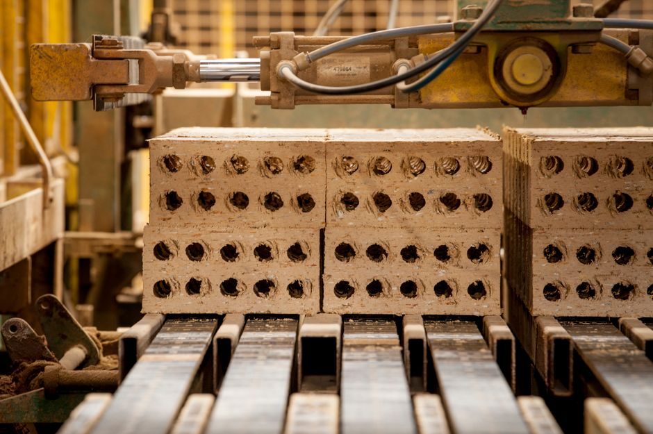
A complete pneumatic system line breaks into four manufacturing tracks: pneumatic actuator bodies, pneumatic cylinder barrels, control-valve blocks, and FRL supply-treatment assemblies — each with its own tolerance band, leak-rate ceiling, and ISO 4414 acceptance test [S2].
Shanghai Hongda Pneumatic System Manufacturing Co., Ltd. typifies the Chinese mid-tier supplier structure, publicly cataloguing its line under four headings: pneumatic actuating components, pneumatic control components, pneumatic supply treatment components, and pneumatic auxiliary components [S2]. That four-bucket taxonomy is also the de-facto bill of materials for any plant doing pneumatic system sourcing audits in 2026.
Actuator and Cylinder Sub-Assembly: Barrel, Piston, Rod, Seal Stack
Cylinder bodies above 50 mm bore are almost universally drawn on aluminium or cold-drawn seamless steel tube (typical 6063-T6 or ST52), honed to a 0.2–0.4 mm wall tolerance and Ra ≤ 0.4 µm internal finish; below 50 mm, extruded aluminium dominates for weight reasons [S2]. Piston rods default to 45# carbon steel with hard-chrome plating 20–25 µm thick, or 304/316 stainless where washdown or pharmaceutical duty rules — an explicit option any control valve manufacturer should publish on its datasheet [S2].
Seal stacks are the spec battleground: NBR for general air at –10 to +80 °C, FKM (Viton-class) for 150 °C process lines, and HNBR for sustained 100 °C duty with ozone exposure. End-cap machining runs on CNC turning centres with ≤ 0.05 mm concentricity on the rod-bearing bore; missing that figure is the single fastest way to spot a low-tier bid [S2].
Control-Valve Sub-Assembly: Spool, Sleeve, Solenoid, Manifold
Directional-control valves split into spool-and-sleeve (5/2, 5/3, 3/2) and poppet designs; spool valves dominate the 0.5–10 bar mid-pressure band while poppet designs take the high-cycle, leak-tight seats above 10⁷ cycles [S2]. Solenoid coils are typically Class F (155 °C) or Class H (180 °C) with IP65 housings, and 24 VDC is now the default machine-builder voltage; 110/220 VAC remains a quarter of catalogue SKUs, mostly for legacy retrofit work [S2].
Manifold blocks on aluminium 6061 or 6063 are machined on 3-axis or 4-axis CNC centres with port-to-port pitch tolerances of ±0.1 mm; anodising is standard, hard anodising 25–50 µm is specified for washdown or marine air. Any sub-assembly of pneumatic control components that ships without a documented leak-rate (commonly ≤ 50 Ncm³/min at 10 bar) should be treated as non-conforming stock [S2].
Supply-Treatment (FRL) Sub-Assembly: Filter, Regulator, Lubricator
The FRL triplet — filter, regulator, lubricator — is the air-quality gate that decides whether downstream cylinders survive their design life. Filters are rated in µm (5 µm and 0.01 µm coalescing are the workhorses) with auto-drain or manual-drain bowls; regulators carry 0.5–10 bar or 0–16 bar output spans with ±0.05 bar repeatability on the better units [S2]. Lubricators are dropping out of new designs in food/pharma where oil-free air is mandated, but remain standard on general factory pneumatics at 1 drop per 300–500 L of airflow [S2].
Bowl materials split polycarbonate (visible, impact-resistant, 80 °C cap) versus metal (aluminium or zinc die-cast, 150 °C+). The spec to lock in writing is ISO 8573-1 air class — Class 7.4.4 for general factory duty, Class 6.4.4 for instrumentation, Class 2.6.4 for pharmaceutical. Vendors who cannot quote the class their FRL delivers to are not yet on a 2026 audit shortlist [S2].
Auxiliary and Piping Sub-Assembly: Fittings, Tubing, Silencers, Sensors
Auxiliary components — push-in fittings, quick-connect couplings, PU/nylon tubing, exhaust silencers, and pressure/vacuum sensors — are the lowest unit-cost line items but drive the highest assembly labour fraction on a pneumatic panel. Push-in fittings in nickel-plated brass or POM (acetal) with metric 4/6/8/10/12 mm O.D. are the 2026 default; BSP and NPT threads persist on imported legacy machines and should be a deliberate, not accidental, choice [S2].
Pressure-switch set-points in the 1–10 bar window with 24 VDC PNP/NPN output are the standard sensor SKU; vacuum switches at –1 to 0 bar cover pick-and-place duty. See also pneumatic conveyor auxiliaries for the dilute-phase conveying line, where silencer and filter sizing diverges from cylinder-panel logic. Sensor repeatability better than ±1 % of full scale is the gate; anything looser is debug-bait on a busy line [S2].
Comparison: Four Sub-Assemblies on Spec Density and Risk
Spec density — measurable, auditable parameters per shipped part — is highest on the control-valve and FRL sub-assemblies, where leak rate, set-point repeatability, and ISO 8573-1 class are non-negotiable; it is lowest on auxiliaries, which is why auxiliaries drive 60–70 % of pneumatic-panel warranty cost despite being roughly 20 % of the bill of materials. Comparison summary: actuators prioritise bore tolerance and seal material; control valves prioritise cycle life and leak rate; FRLs prioritise filtration grade and pressure repeatability; auxiliaries prioritise fitting standardisation and tubing material. Reverse-engineering any pneumatic BOM into those four risk buckets is faster than reading ten vendor catalogues [S2].
Process Standards, Audit Gates and Failure Modes
ISO 4414 governs general pneumatics safety and is the baseline audit reference; ISO 8573-1 sets the air-purity class the FRL must deliver; ISO 5599 covers valve interface dimensions on the larger 5-port sizes. The common failure modes seen on a 2026 production line are: seal extrusion on cylinders run above 8 bar, solenoid coil burn-out on valves left energised beyond their duty cycle, and FRL bowl cracking on polycarbonate parts exposed to solvents — all of which are traceable to a missing parameter on the purchase spec, not a defect in the part itself [S2].
For additive-manufacturing material work that has crept into pneumatic prototyping — manifold blocks, sensor brackets, end caps in PA12 or PA-GF — sintering density above 95 % and a documented leak-test on first article are now the floor for a 2026 acceptance test. Tier-2 suppliers like Beco Manufacturing round out the multifunction process calibrator and assembly-tools side of pneumatic panel build, and belong on the same sourcing sheet as the pneumatic OEMs themselves [S1].
Audit gate to lock into a 2026 P.O.: ISO 8573-1 class declared in writing, leak rate ≤ 50 Ncm³/min at 10 bar on every valve, seal-material and temperature range per cylinder, and a documented FRL sizing calculation against the worst-case actuator count. For related sourcing context on smart-factory rollout, see Hydraulic Smart Manufacturing 2026; on adjacent automated-material-flow spec sheets, see Mining Equipment Smart Manufacturing 2026; and on silencer/spray-nozzle overlap with tank-cleaning duty, see Tank Cleaning Machine Sizing and Selection.