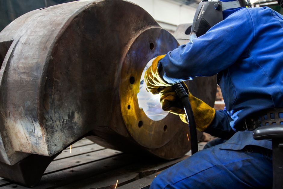
Precision air conditioning (PAC) units built for server rooms, modular data centers and laboratories are specified to control temperature within ±0.5°C and relative humidity within ±3.0% RH around setpoint, with a design life exceeding 10 years and 24/7/365 duty [S2].
That envelope, tighter than the ±1–2°C typical of comfort HVAC, is achieved by combining inverter-driven scroll or digital-scroll compressors, EC (electronically commutated) fans, hot-gas bypass, electric reheat and microprocessor controllers [S2]. Manufacturing such a unit is a multi-band flow rather than a single assembly line, and the bands differ markedly from comfort-air-conditioning production.
Definition and scope: what counts as a "precision AC" unit
PAC, also called close-control air conditioning, is the class of cooling equipment specified for server rooms, telecom base stations, cleanrooms and laboratories where the load is dominated by sensible heat and where temperature and humidity must stay inside a tight band [S2][S4]. Product variants in current catalogues split into data-center precision ACs, in-row precision ACs, rack-mounted precision ACs, outdoor-cabinet precision ACs and laboratory high-precision ACs [S2].
The functional difference versus a comfort rooftop or split unit is the control resolution and the redundancy architecture: a PAC must hold ±0.5°C / ±3.0% RH across changing IT load, support hot-aisle/cold-aisle containment, and pair with rack-side or rear-door heat exchangers in liquid-cooled deployments [S2]. That scope sets the manufacturing bands that follow.
Band 1 — Sheet-metal and chassis fabrication
Chassis fabrication starts with galvanized or cold-rolled steel (typical 1.0–1.5 mm for panels, 1.5–2.0 mm for frames) and aluminium for indoor coil casings, blanked on turret or laser cells and formed on CNC press brakes. Tolerance bands for the air-handling section are held at ±0.5 mm on mounting faces so that evaporator coils, fan walls and filter racks register on a common datum [S3].
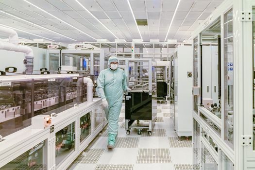
Compared with comfort HVAC, the precision variant uses higher panel flatness and tighter hole-pattern tolerance because the unit must seal against bypass air — leakage directly degrades the ±3.0% RH control claim [S2]. In-row and rack-mounted SKUs add aluminium extrusion frames that are machined to ±0.1 mm for slide-rail engagement; the precision here pushes chassis work into the same tolerance band as light precision manufacturing for semiconductor fabs, where Taniguchi-curve processes like single-point diamond turning and CMP are evaluated at the nanometre scale [S3].
Band 2 — Heat-exchanger coil and refrigerant-circuit assembly

Evaporator and condenser coils are typically copper tube (9.52 mm or 12.7 mm OD) with hydrophilic-coated aluminium fins, expanded on hydraulic expander stands to 0.05–0.10 mm interference fit. Circuit design for a 20–80 kW in-row PAC uses 4–8 circuits with dual-row distribution to keep refrigerant velocity inside the 2–6 m/s band that optimises heat transfer without carrying oil out of the compressor [S2].
Assembly work is torque-critical: flare and brazed joints are N2-purged during brazing (oxygen-free phosphorous-copper or silver brazing alloy 45% Ag) and leak-checked to ≤3 g/yr at 3.0 MPa N2 hold. The compressor — inverter scroll or digital scroll in the 3–15 kW range for in-row, fixed-speed scroll up to 40 kW for room-level units — is mounted on rubber isolators selected so the lowest excitation mode sits above 35 Hz, away from the fan's 20–28 Hz operating band [S2].
Band 3 — Fan wall, filter rack and air-side integration
Air-side assembly is where the EC-fan array is mounted. EC fans in current PACs run 1500–3500 rpm modulated by 0–10 V or Modbus, with 30–50 Pa external static capability to push through a 4-inch deep F7/F9 filter rack and a chilled-water or DX coil [S2].
Filter sealing is a common failure point: gasketed channels are specified at 3 mm compression, and the rack is sized to ≤2.5 m/s face velocity to keep filter pressure drop inside the 50–250 Pa operating window. Humidification (electrode boiler or infrared steam canister) and electric reheat banks (typically 3–9 kW in 1 kW steps) are wired and insulated before the unit moves to controls integration [S2].
Band 4 — Controls, sensors and electrical integration
Every PAC carries a microprocessor controller (commonly an OEM-branded BACnet/Modbus device) that reads return-air temperature, return-air humidity, supply-air temperature, filter ΔP and compressor suction/discharge pressures. Sensor accuracy needs to match the unit's control claim: a ±0.3°C RTD or thermistor on supply air is required to deliver the ±0.5°C room control without overshoot [S2].
Electrical build is to a defined spec — IP54 control box minimum, surge protection on power and communications lines, and a power distribution block rated for the inverter's harmonic profile. Liquid-cooled variants of the PAC line integrate a chilled-water or rear-door heat-exchanger control loop, and the controls build must bring the secondary loop's flow switch, leak sensor and three-way valve into the same BMS map as the air-side I/O [S2].
Band 5 — Charge, burn-in, performance and environmental test
Final assembly starts with a vacuum pull to ≤200 µm Hg for at least 30 minutes, followed by a refrigerant charge to nameplate mass (typically R-410A or R-32, 2–8 kg depending on capacity) weighed on a refrigerant scale to ±10 g. Units then go to a run-test cell where they operate for a minimum 4-hour burn-in at ARI/Eurovent-equivalent conditions: 35°C ambient return, 24°C dry-bulb / 17°C wet-bulb entering evaporator, until the controller's multifunction process calibrator-checked sensor channels track within tolerance [S2].
Acceptance data recorded per unit include sensible and total cooling capacity, kW input, EER, leaving air dry-bulb and humidity, superheat, subcooling and supply-air ΔP. Humidity-control verification is a separate 30-minute step where the humidifier is exercised to confirm ±3.0% RH control band. Units failing any check are routed back to a rework station — typically <5% on a mature line. This burn-in step is the closest thing the PAC factory has to the metrology gates used in DRAM cell production, and it is the gate that turns a chassis into a precision AC [S3].
Selection criteria: who the PAC line is built for, and who it is not
PAC manufacturing is built for OEMs serving data centres, telecom base stations, banks, hospitals, government and university IT rooms — verticals where the customer signs off on a ±0.5°C / ±3.0% RH performance guarantee [S2]. It is not the right line for a builder of residential splits, automotive bus AC or comfort rooftop units, which use commodity scroll compressors, single-speed fan motors and a ±1–2°C control band; the bill of materials, burn-in time and unit ASP are all higher on a PAC line [S1][S2].
Within the PAC family, decision criteria for a buyer are: capacity band (5–120 kW), air-cooled vs chilled-water, floor-standing vs in-row vs rack-mount, efficiency (EER 3.0+ on premium SKUs), and integration with the rest of the modular data centre (UPS, PDU, cold-aisle containment). The manufacturing line has to support all variants without re-tooling between SKUs, which drives the use of a common base frame and modular coil/fan sections [S2].
Option comparison across the five main PAC form factors
Five form factors dominate current PAC catalogues, and the choice between them is a manufacturing question as much as a deployment one [S2].
Data-center precision AC (floor-standing, 20–120 kW): highest capacity, longest lead time, full redundancy fans and compressors; targets hyperscale and colocation halls. In-row precision AC (10–60 kW): sits between server racks, 300 mm or 600 mm wide form factor, short refrigerant runs, easier service; targets enterprise and edge. Rack-mounted precision AC (3–12 kW): slides onto the rack top or into a zero-U slot, single-phase power, limited reheat; targets single-rack edge and micro data centres. Outdoor-cabinet precision AC (5–30 kW): IP55 enclosure, integrated condenser, low noise; targets outdoor telecom and 5G base stations. Laboratory high-precision AC (5–40 kW): tighter ±0.3°C and ±2.0% RH variants with redundant humidifiers and HEPA options; targets pharma and metrology labs [S2].
Across these, the shared process bands are sheet-metal, coil/circuit, air-side, controls, and charge-and-test; the differences are in burn-in duration, sensor count and the type of pressure/leak test demanded by the customer's SLAs. Choosing a line optimised for in-row means tooling up for 300/600 mm modular frames; choosing laboratory means adding a higher-grade precision filter stage and a humidity calibration cell. There is no single "best" PAC form factor — the right answer is the one that matches capacity, footprint and redundancy to the room [S2].
Limitations, failure modes and sourcing
Three failure modes dominate field returns on PAC units: refrigerant leaks at brazed joints, filter ΔP drift that pushes the EC fan off its efficiency sweet spot, and humidity-sensor drift that breaks the ±3.0% RH claim. Manufacturing mitigations are N2-purged brazing with documented leak-rate acceptance (≤3 g/yr), pre-shipment filter inspection, and a humidity calibration step against a chilled-mirror reference [S2].
Quality system reference: ISO 9001-registered manufacturing is the floor for any OEM serving North American bus, commercial and EV markets [S1]. Specific safety standards for refrigerant containment, electrical safety and EMC are typically applied at the unit level (regional variations apply; the research did not name a single harmonised standard, so no standard number is asserted here). For an OEM evaluating a PAC line build-out, the practical sourcing checklist is: coil suppliers capable of holding ±0.05 mm tube-to-fin interference, EC fan suppliers with proven 50,000-hour L10 life data, controller firmware that exposes BACnet/Modbus points, and a test cell with a calibrator-traceable reference for the burn-in acceptance [S2].
Trackable signals to watch over the next two quarters: (1) the move from R-410A to lower-GWP R-32 and R-454B charges in 5–40 kW PAC SKUs, which will require updated vacuum and recovery procedures on the line; (2) the integration of rear-door heat-exchanger control loops into the same controller map as the air-side I/O, mirroring the liquid-cooling factory pattern; (3) tighter supplier-side lot traceability on inverter compressors, where EC-fan and inverter-compressor pairing increasingly determines the unit's part-load EER.
For component-level specifications, see additive manufacturing material.