Immersion cooling in 2026 is, at its core, a four-bill-of-materials build: a stainless or coated steel tank, a dielectric fluid, a fluid-handling loop with redundant pumps and a coolant-to-water heat exchanger, and a server SKU whose thermal interface material (TIM), plastics, capacitors and cable jackets have all been qualified against the chosen fluid [S2][S6].
The Open Compute Project whitepaper frames it bluntly: most IT equipment is still designed and built for air, so a manufacturer adopting immersion has to re-qualify materials, redesign mechanicals for buoyancy and pump-induced vibration, and validate power and data connectors that survive continuous dielectric contact [S2]. The result is a manufacturing process that sits halfway between a process skid and a data-center rack build.
Two process routes: single-phase loop vs. two-phase boiling
Single-phase immersion uses a dielectric liquid that stays liquid across the operating range; heat is absorbed by sensible heating and the warm fluid is pumped to a heat exchanger where the heat is rejected to a facility water loop [S6]. This is the route used by Submer's SmartPod product family, by the broader "Submer Cools" branded product line described on the company's immersion cooling page, and by reference designs from Inventec, Intel and the Open Compute Project [S3][S5][S6].
Two-phase immersion uses a low-boiling-point fluorinated fluid (classically 3M Novec 649) that boils off the chip surface; vapor rises, condenses on a lid-mounted or external condenser, and returns as liquid, with gravity or a pump-driven return path [S1]. The LBNL DoD demonstration (May 2016, document LBNL-1005666) reports that the two-phase test bed met energy-efficiency and GHG-reduction targets but hit IT-equipment failures and cost issues that the authors flagged as a blocker to commercialization at that time [S1]. That finding shapes the 2026 mix: single-phase is mainstream, two-phase is concentrated in research and high-power-density HPC racks.
Tank, frame and form factor: from 12U reference to hyperscale pods
The reference mechanical envelope is a 12U tank. Intel's Open IP Immersion Cooling - Single Phase - 12U brief (document 765931, revision 1.0) specifies a tank of 815.5 mm L x 871.0 mm W x 1333.0 mm H, designed to accept both 19-inch and 21-inch server sleds and to scale in 12U increments to 24U, 36U and 48U before stacking into pod-level assemblies [S5]. The OCP guideline adds the design point that immersion rack enclosures are often quite different from traditional air racks, with buoyancy forces, lid sealing, fluid entry/exit manifolds and condensed-water management all driving mechanical redesign [S2].
Submer's product family follows the same pod logic: SmartPod EVO and SmartPod EXO are modular immersion-cooling units pitched at hyperscale and edge buildouts, with services covering design, build and lifecycle fluid management (the company's "Labs / Design & Build / Rubix / Inferx" service stack) [S3]. For a manufacturer evaluating line architecture, the practical takeaway is that tank width is set by the widest server sled you intend to qualify, height is set by the pump-and-filter service interval you want, and depth is set by the length of the longest immersion-rated power whips and network cables.
Fluid selection: hydrocarbons, fluorocarbons and the TIM compatibility trap
Fluid choice is the single biggest materials-engineering decision. Single-phase systems use either engineered hydrocarbons (low-viscosity, lower cost, often used by Asian OEMs and Submer-style deployments) or fluorinated dielectric fluids (higher dielectric strength, higher cost, broader chemical compatibility) [S2][S6]. The OCP guideline notes a clean split in requirements: single-phase hydrocarbons/fluorocarbons vs. two-phase fluorocarbons are not interchangeable in qualification, and the supply chain has to be qualified separately for each [S2].
The second-order failure mode is the thermal interface material. Indium Corporation's immersion-cooling application note states explicitly that dielectric fluid dissolves organic compounds in conventional TIMs over time, contaminating the fluid and loading the filter, and that polymer-based thermal greases eventually degrade and are not recommended; metal-based preforms (Indium's Heat-Spring line) are cited as the proven alternative across all immersion fluids [S8]. For a manufacturer, that drives a controlled-bom rule: no thermal grease, no silicone potted inductors that outgas into the bath, no PVC-jacketed cabling, and a documented fluid-compatibility matrix covering every polymer, elastomer and adhesive in the sled.
Loop architecture: pump, filter, heat exchanger and instrumentation
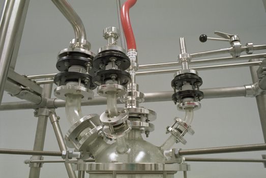
The process loop is essentially a chiller skid adapted for a dielectric. A typical single-phase build uses centrifugal or magnetic-drive pumps sized for the fluid's viscosity and specific heat, particulate and sorption filters to capture TIM debris and any outgassed species, a plate or coaxial heat exchanger rejecting to facility water, and instrumentation on temperature, pressure, flow, leak detection and fluid level [S4][S6]. The KTH/Diva hyperscale feasibility study walks the same refrigeration-cycle logic applied in reverse: a compressor and condenser in a vapor-compression chiller become unnecessary in single-phase immersion, but the heat-exchanger stage is conceptually identical to a chiller's evaporator side, with the same control loop on coolant temperature and pressure differential across the expansion valve [S4].
The instrumentation stack overlaps heavily with industrial process control. Temperature and pressure transmitters on the loop, flow meters on the facility-water and dielectric sides, and isolation valves on each tank for service isolation are standard; the pressure transmitter, flow meter and industrial valve categories apply directly. The control architecture also borrows from the broader liquid-cooling manufacturing stack, and process-engineers planning a line should cross-reference the liquid cooling smart manufacturing reference design for cold-plate, heat-sink and digital-twin specs that translate to immersion-side heat-exchanger design.
Manufacturing process flow: from frame weld to factory fill
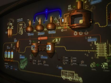
Putting it together as a process map, an immersion-cooling skid build breaks into seven stations: (1) tank fabrication and leak test, typically stainless or coated mild steel with welded or gasket-sealed lids; (2) pump, filter and heat-exchanger skid assembly, plumbed and pressure-tested dry; (3) tank instrumentation fit-out, with the pressure transmitter, level sensor, temperature probes and leak detector wired to a PLC or BMS; (4) facility-water and dielectric loop tie-in, including the isolation industrial valve set; (5) server sled integration on a parallel line, where every component is checked against the fluid-compatibility matrix and TIMs are applied as metal preforms rather than grease [S8]; (6) closed-loop factory fill, degas and burn-in, with the dielectric circulated through the filter array until particulate and moisture meet the release spec; (7) final acceptance test, with a flow meter verifying loop ΔP vs. rated curve and a thermal soak under load.
Steps 1-4 are essentially multifunction process calibrator territory for the instrument technician: every temperature, pressure and flow device has to be trimmed against the actual fill fluid, not air, because dielectric viscosity and density shift calibration. Step 5 is where the line most resembles a v-process line or other disciplined electronics assembly line, with a controlled-bom gate, a fluid-compatibility traveler and a serialized record of every component that contacts the bath. Step 6-7 is the leak-and-burn gate; the additive manufacturing material reference is useful here only insofar as AM-printed manifold brackets and flow-optimized impellers are now being specified in some hyperscale reference designs, though the additive manufacturing material choice must also be qualified against the chosen dielectric.
Selection criteria and a side-by-side comparison
Four criteria dominate the build-vs-buy decision for a manufacturer evaluating immersion: thermal target (heat flux per cm^2 of silicon), fluid class, qualification scope, and service interval. A simplified comparison based on the cited reference designs: [S1]
- Single-phase hydrocarbon (Submer / Inventec style): moderate thermal headroom, lowest fluid cost, easiest qualification for commodity server SKUs, filter service typically 6-12 months, broad polymer-elastomer compatibility risk to be screened [S3][S6].
- Single-phase fluorinated: higher dielectric strength and chemical stability, higher fluid cost, well-suited to mixed-vendor sleds, same single-phase loop architecture, longer fluid service life [S2][S6].
- Two-phase fluorinated (Novec 649 / engineered replacement): highest heat-flux capability, condenses heat passively on the lid, smallest pumping load, but requires a sealed vapor path and, per the LBNL study, has historically been gated by IT-equipment reliability and cost issues [S1].
- Reference-design Open IP (Intel 12U, OCP guideline): not a fluid choice but a mechanical and qualification framework; the 12U tank envelope (815.5 x 871.0 x 1333.0 mm) and 19/21-inch sled compatibility are the practical adoption gates [S2][S5].
Limitations, failure modes and who should not adopt
Immersion is not a universal fit. Supermicro's immersion-cooling glossary entry flags leak risk, the need for responsible disposal and recycling of used dielectric fluids, and the requirement for immediate response to any breach to prevent hardware damage [S7]. The OCP guideline adds the constraint that pump-induced vibration, buoyancy on lighter components, and condensation management on power and data connectors all introduce new failure surfaces that an air-cooled SKU has never seen [S2]. The LBNL DoD report is more pointed: two-phase immersion with Novec 649 was not viable at the time of the demonstration because of IT-equipment failures and cost, even though the energy-efficiency and GHG-reduction performance objectives were met [S1].
For a manufacturer, the practical "do not adopt" profile is: low rack density (under ~15 kW per rack as a rough order of magnitude), no on-site industrial water for the heat-exchanger reject loop, restricted access to qualified fluid-recycling services, or a server SKU set with too many unqualifiable polymer components (potting compounds, PVC jackets, silicone gaskets) to clear the controlled-bom gate without a major redesign. The "adopt" profile is the inverse: hyperscale or HPC workloads, available facility water, a tight fluid-management service contract, and a sled platform already designed or co-designed for immersion from the PCB up.
Standards, sourcing and what to track next
The OCP immersion guideline is the closest thing to a public specification, covering material compatibility, thermal design, mechanical design and electronics-design chapters authored by 2CRSI, 3M, Wiwynn, Asperitas, Flex, Intel and Vertiv [S2]. Intel's 765931 product brief supplies the mechanical reference numbers (815.5 x 871.0 x 1333.0 mm tank, 12U to 48U scale-out) for any builder aligning to the Open IP family [S5]. On the fluid side, suppliers such as 3M (historically Novec 649), Inventec Performance Chemicals and the in-house Submer brand set the dielectric chemistry, and the Indium Heat-Spring line is one of the cited metal-TIM alternatives compatible with both hydrocarbon and fluorinated baths [S3][S6][S8].
Two signals worth tracking in the second half of 2026: any update to the OCP guideline revision history beyond the 1.01 of December 2020, since that document is the de facto open reference for builders [S2]; and the commercial maturation of two-phase immersion for HPC and AI-training workloads, where the LBNL-style reliability blockers have historically been the gating issue and where the high heat-flux payoff is largest [S1]. For a manufacturer planning a line build, the immediate engineering work is the fluid-compatibility matrix and the metal-TIM decision, not the tank size.