Pressure switch specification is dominated by six decision nodes — element type, set-point range, deadband, wetted materials, electrical rating, and hazardous-area approval — and the wrong call on any one of them produces nuisance trips, contact welding, or premature sensor failure in the first year of service [S1].
The market spans mechanical diaphragm/bourdon/piston switches, electronic solid-state transmitters with switch outputs, and differential variants for filter and heat-exchanger monitoring, with HS code 9032.20.00.00 covering pressure switches used in diesel-truck braking-system pressure control [S4] and adjacent codes 9026.20 and 9032.81 covering related switching and control functions [S4]. Both OEM catalogues and industrial sourcing platforms list mechanical and electronic units as distinct, non-interchangeable lines [S1][S2].
Switching Element: Mechanical vs Electronic vs Differential
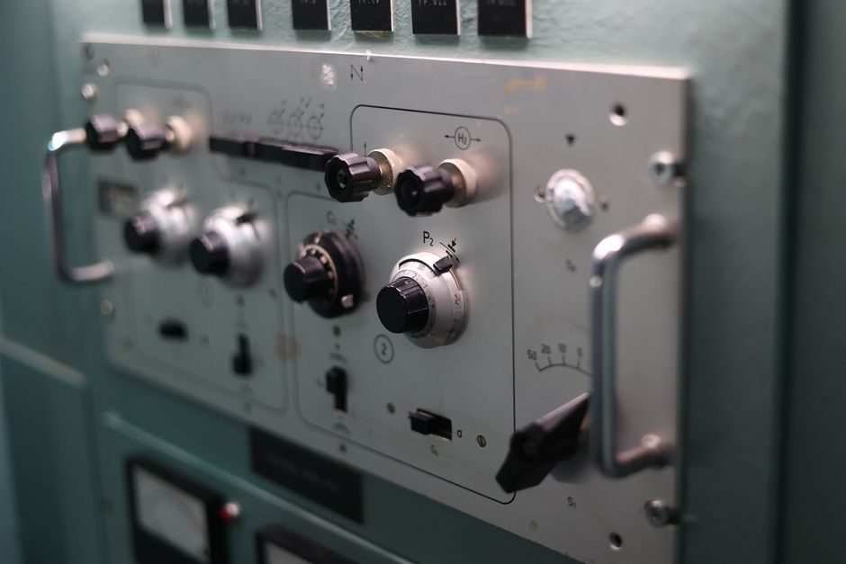
The two architectures do not behave the same on a process line: mechanical units trip at a single adjustable set-point with a fixed mechanical deadband, whereas electronic units allow programmable set-points, narrower deadbands, and analog readback through the same cable [S1].
For hydraulic and pneumatic machinery, mechanical piston or diaphragm switches remain the dominant factory-floor choice because they tolerate voltage spikes from contactor coils, and the WIKA product overview treats them as the default category for industrial on/off control [S1]. For OEM equipment with onboard PLCs, a switching pressure transmitter such as the JCS model published on CENS replaces the mechanical switch plus separate gauge with one device that outputs a switched signal and an analog reading [S2][S3]. Differential pressure switches form a third category dedicated to filter-clog, heat-exchanger, and lubrication-circuit monitoring where the controlled variable is Δp, not absolute line pressure [S1].
Set-Point Range, Deadband, and Proof Pressure
Set-point range, deadband (the difference between trip and reset pressures), and proof pressure (the over-pressure the element survives without calibration shift) are the three numbers that determine whether a switch survives its application [S1]. Selecting a unit with a set-point range that is too wide for the working pressure forces the user to adjust near the extreme end of the spring scale, where repeatability degrades and contact life drops [S1].
Deadband is the most commonly underspecified parameter: a tight deadband (typically under 5% of set-point) is required for pump cut-in/cut-out cycling, but a wider deadband is acceptable for over-pressure alarm-only service where chatter would destroy the contacts in weeks [S1]. Comparing the available options on a single decision matrix — set-point range, deadband percentage, proof pressure ratio, and wetted material — gives the engineer a defensible choice in a single table rather than across three datasheet pages [S1].
Wetted Materials and Process Connection

Wetted-parts compatibility is decided by the process fluid, not the pressure rating, and a pressure switch that performs on water will fail in months on sour crude, amine, or sodium hydroxide service [S1]. OEM catalogues typically list 316L stainless steel as the default wetted material and offer alternatives such as Hastelloy, Monel, or PTFE-coated diaphragms for corrosive or abrasive media [S1].
Process connection size and thread form must match the existing tapping — common fractional NPT and BSP threads for general industrial service, and high-pressure cone-and-thread or autoclave fittings for wellhead and downstream-petrochemical duty [S1]. For OEM replacement on excavator electric systems, sourcing platforms list switches against specific equipment part numbers such as 206-06-61130 for PC300-8, which encodes both the set-point and the connector form factor [S5]. When the application involves clean steam, pharmaceutical water, or hygienic service, a sanitary tri-clamp or aseptic flange connection is mandatory and a standard NPT switch will not meet the local surface-finish requirement [S1].
Electrical Rating, Output Type, and Compatibility with the Control System
The electrical rating of a pressure switch — voltage, current, and switching duty (resistive, inductive, or motor load) — must match the coil or input it drives, and underspecifying the contact rating is the most common cause of field failure within the first six months [S1]. Mechanical switches typically publish ratings in the 5 A at 250 VAC range for general-purpose microswitches, with lower ratings for DC inductive loads due to arcing [S1].
Electronic pressure switches commonly offer a PNP/NPN transistor output for direct PLC input, a relay output for higher loads, and a 4-20 mA analog output for trending [S1]. HART communication is layered on the 4-20 mA loop as a frequency-shift-keyed signal, while Foundation Fieldbus and PROFIBUS PA replace the analog current with a fully digital bus — the two architectures are not compatible on the same wiring [S1]. Specifying a HART-output switch on a PROFIBUS PA segment, or a PNP output on a 24 V PLC input designed for a sourcing (PNP) or sinking (NPN) device, will produce a wiring-up error that surfaces on first power-on. The pressure switch category page covers the full list of output protocols, including which are digital bus replacements for the 4-20 mA loop.
Hazardous-Area Certification and Standards Mapping
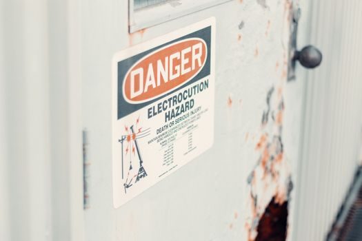
For any switch installed in zone-classified areas, the certification mark on the nameplate (ATEX 2014/34/EU for Europe, IECEx for international, and the relevant NEC 500/505 class/division or zone system for North America) must cover both the gas or dust group and the temperature class expected in service [S1]. Sourcing outside the certification envelope is a contractual rejection in most EPC projects and an unsafe installation in any retrofit.
For sour service (H₂S-bearing fluids), NACE MR0175 limits the materials and hardness of wetted parts, and the same standard governs selection of the pressure switch wetted path as much as it governs industrial switch bodies and connecting tubing [S1]. For fire-safe or double-block-and-bleed isolation, API 6D and ASME B16.34 specify the valve-side requirements, but the pressure switch on the bleed port follows the same metallurgical constraints [S1]. Selecting the certification first and the electrical second is the safest order, because adding Ex d flameproof enclosure as a field retrofit on a non-certified switch is rarely accepted by the certifying body.
Application Segments: Where Each Architecture Wins
Mechanical diaphragm and piston switches are the default for pump cut-out, compressor unload, and hydraulic-system over-pressure alarm on general industrial machinery, with WIKA listing this as the largest application segment in its 2026 product overview [S1]. Electronic pressure switches dominate OEM equipment with onboard PLCs, where one device replaces a mechanical gauge plus a separate switch and provides a 4-20 mA signal for the HMI [S1][S2].
Differential pressure switches are specified almost exclusively for filter-clog indication, lubrication-circuit health monitoring, and heat-exchanger fouling alarms — applications where the controlled variable is the pressure drop across a component rather than line pressure [S1]. On mobile machinery such as excavators, the switching sensor doubles as a diagnostic input and is part-number-locked to the machine harness, which is why aftermarket part numbers such as 206-06-61130 for the PC300-8 carry set-point, connector, and connector-pinout information encoded into the SKU [S5]. For process-plant isolation duty, an isolating switch on the same skid handles the lock-out requirement independently of the trip-pressure switch.
Decision Comparison: Mechanical vs Electronic vs Differential

Lining the three architectures up against four decision criteria gives a one-glance selection: mechanical piston/diaphragm on cost per set-point and overload tolerance; electronic pressure transmitter with switch output on deadband precision and analog readback; differential pressure switch on filter/heat-exchanger service specifically [S1]. On overload tolerance, mechanical units survive over-pressure excursions without sensor damage, while electronic units require proof-pressure rating to be checked against water-hammer or pump-surge transients [S1]. On output, mechanical is a single SPDT or DPDT contact, electronic is PNP/NPN/relay/4-20 mA in combination, and differential is a single SPDT contact in the standard form [S1].
For level-switch duty in a vessel, the level switch product family covers buoyancy, capacitive, and tuning-fork alternatives that are outside this pressure-switch scope but are sometimes confused at the specification stage. For a discrete on/off limit on a mechanical actuator, the limit switch family is the position-based counterpart, not the pressure-based one.
Common Failure Modes and Specification Pitfalls
Three failure modes dominate the warranty data: contact welding on inductive DC loads above the published rating, set-point drift after proof-pressure excursions beyond the datasheet value, and diaphragm fatigue cracking from high-cycle pump applications [S1]. Each maps to a specific datasheet number that the specifier must check before purchase.
Specifying a switch on a load-break motor starter coil without an interposing relay, on a proof pressure below the pump dead-head rating, or on a duty cycle above 30 cycles/minute all produce failures that surface inside the first year of service [S1]. A final sanity check is the load switch rating if the pressure switch is wired as the upstream interrupting device rather than as a trip signal to a downstream contactor — the two are distinct IEC/UL device categories with different test profiles.
The next decision node is the SIL rating for safety-instrumented-function service — IEC 61508 SIL 1, 2, or 3 — which most general-purpose mechanical and electronic pressure switches do not carry and which forces a move to a separately certified line of devices when the application is a SIF rather than a basic control loop.