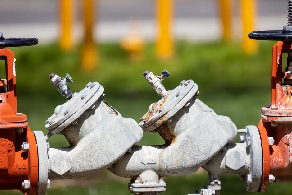
Pressure reducing valve selection is a three-variable problem: design flow rate, allowable pressure drop across the valve, and a permissible flow velocity window that keeps noise and erosion in check; the published chart on every PRV datasheet is just the graphical intersection of those three.
For domestic water, the working velocity band is 1–2 m/s through the valve passage, with downstream pressure droop kept gradual rather than stepped, and a target Cv derived from the simple liquid relation Cv = Q / √ΔP, where Q is in GPM and ΔP in psi [S3][S4].
What the chart actually shows
A PRV sizing chart is a family of curves, one per nominal size (DN15, DN20, DN25, DN32, DN40, DN50 and up), plotting allowable flow on the X axis against the resulting pressure drop (or downstream pressure droop) on the Y axis, typically annotated in m³/h or l/s against bar or kPa [S3].
The intersection of the design flow rate with each size curve yields a ΔP, and the specifier picks the smallest body size whose ΔP is still inside the system designer’s allowable droop budget, commonly 0.2–0.5 bar at design flow, not at zero flow [S3]. TLV publishes a parallel set of "equipment connection sizing" curves for its direct-acting PRV line, framed as adjustable flow ranges per connection size when reducing 0.5 MPaG down to 0.3 MPaG (72.5 to 43.5 psig), so each DN has a clear min/max flow band rather than a single rated point [S2].
Inputs you must lock before reading any chart
Five variables gate every PRV sizing calculation: upstream pressure, downstream set pressure, flow range, fluid (with temperature and density), and the allowable downstream pressure variation at peak load [S6]. The mistake most spec sheets make is treating nominal flow as design flow; the Caleffi-derived method explicitly multiplies a fixture-unit total by a simultaneity factor that drops as fixture count rises, because the assumption "everything open at once" inflates pipe and valve size and worsens dead-end water age [S3].
Working example from the field: 10 GPM at 120 psi inlet, 75 psi set pressure, 65 psi at target flow, which is a 10 psi droop or roughly 14% of setpoint, well inside the typical 10–20% droop band a direct-acting PRV can hold without going into wiredrawn failure mode [S7]. The IEC 60079 / ATEX-certified lines used in hazardous-area PRV pilots are a separate procurement track and do not change the hydraulic sizing; the explosive-atmosphere certification sits on top of the same Cv/Kv curves.
How to read Cv/Kv and convert between fluids
Cv (US convention) is the water flow in GPM through the valve at 1 psi ΔP; Kv (metric) is the water flow in m³/h at 1 bar ΔP, and the two convert as Cv ≈ 1.156 × Kv [S4]. For steam, air, and other compressible fluids the simple Cv = Q / √ΔP no longer holds, and the calculation must account for the critical pressure ratio (roughly 0.5 for saturated steam at 10 bar g in the Spirax Sarco worked example) plus a specific volume correction, otherwise the chart will over-promise flow by 20–40% [S5].
The first-principles nozzle analogy in the Spirax Sarco training module shows the same chart geometry, but with choked-flow lines drawn in, so the specifier can see the operating envelope end where further ΔP no longer buys more mass flow, a curve shape that direct-acting PRVs for steam typically run right up against at part load [S5].
Direct-acting versus pilot-operated on the same chart
Direct-acting PRVs (diaphragm-on-spring, no external pilot) show steeper droop curves and tighter flow ranges per body size, which is why TLV publishes per-DN adjustable ranges rather than one universal curve [S2]. Pilot-operated PRVs (pilot stage drives the main piston) flatten the droop curve dramatically, often holding within 5% of setpoint across 10–100% of rated flow, but they cost more and need a sense line and, on steam, a strainer ahead of the pilot screen.
For domestic water at 1–2 m/s, a direct-acting DN25 or DN20 body is usually enough up to about 2–3 m³/h, beyond which the velocity climbs past 2 m/s and noise plus seat wear accelerate; a pilot-operated unit becomes the right answer when flow range exceeds roughly 5:1 from minimum to design, which is common in tall buildings and district steam branches [S3][S2]. A related pneumatic sizing discipline applies when the PRV is used to supply a pneumatic actuator downstream, where the same Kv logic governs but the fluid is instrument air at 4–8 bar, see the Pneumatic Actuator Datasheet Parameters breakdown for the actuator-side torque and air-consumption side of that loop.
Failure modes when the chart is misused
Oversizing is the more common error: the valve lands in a near-closed seat position at normal load, the seat and disc erode, downstream pressure creeps, and the relief pathway (or a separate safety relief valve on the downstream header) starts to lift under no-flow conditions. Undersizing shows up as the opposite: droop past 20% of setpoint at peak demand, the valve chatters, and the diaphragms fail in months rather than years. [S3]
Choked flow on steam service is a third category: the chart says 800 kg/h at 8 bar ΔP, but the actual steam mass flow stalls around 520 kg/h because the valve has passed its critical pressure ratio, and the downstream heat exchanger starves [S5]. Always cross-check that the operating point on the chart sits to the left of the choked-flow line for compressible service.
Sanity-check the chosen size with two free tools
Watts publishes a PRV sizing calculator for North American plumbing and hydronic lines, keyed off pipe size, inlet pressure, outlet setpoint, and design flow, with a built-in velocity check against the same 1–2 m/s target [S1]. For steam and air, the TLV adjustable-range tables per connection size provide the cross-check, and a vendor-issued Cv chart then confirms the droop at design flow before purchase order is released [S1][S2].
The structural logic generalises across fluid types: water PRVs sit on velocity-limited curves, steam and air PRVs sit on mass-flow / ΔP curves with a critical-flow cap, and the chart in every datasheet is just the graphical form of one Cv equation solved across the body-size family. A working specifier’s habit should be: pick two candidate sizes, read ΔP at design flow on both, then verify the second candidate also holds droop within 10–20% of set at the minimum guaranteed load. If both pass, the larger one is the safer buy for unknown future load growth, and a downstream pressure reducing valve on the same chart, one DN smaller, is the usual trim for critical branch circuits.
Spec-level background on the components involved: checking and testing apparatus.