
Installing an electric rebar cutter cleanly is a 10-step procedure: confirm the 3-phase supply matches the nameplate, anchor the base to a level concrete pad, verify blade-to-anvil gap per the model's cut-capacity chart, then run a no-load and a graded-load test before production cuts [S1][S3].
Cutters in the 10–42 mm rebar band, such as the TAEYEON B&C TYC-HD19A and TYC-NHD25 platforms, draw single- or three-phase power depending on model and ship with blade sets rated to the bar diameter they cut [S1]. Correct installation prevents the three most common first-week failures: chipped blades, sheared mounting bolts, and motor overload trips.
Pre-Install Survey: Capacity, Power, and Site
Match the cutter's rated bar diameter to the heaviest rebar grade on the project's bar list before unpacking — a machine rated to 25 mm cannot be pushed to 32 mm without blade-chip risk [S1]. The Philippine supplier network, led by CNB Machinery as the exclusive TAEYEON B&C distributor, stocks electric bar cutters across the 10–42 mm range with nameplate capacities tied to specific blade-set SKUs [S1].
Power requirements follow the size class: portable 10–16 mm cutters commonly run on 220 V single-phase, while 25–42 mm machines require 380–415 V three-phase with a dedicated breaker sized to the motor full-load current listed on the nameplate [S1]. Site selection needs a 600 mm clearance around the blade housing for bar feed and swarf discharge, plus a level concrete pad rated for at least 1.5× the machine's net weight to absorb cyclic cutting shock.
Mechanical Mounting and Anchoring
Anchorage is the most skipped step and the root cause of most first-month alignment failures. The base plate is bolted through M12 or M16 expansion anchors — 4-bolt pattern on portable units, 6-bolt on 32–42 mm machines — torqued to the OEM value, typically 80–120 N·m for M12 and 180–250 N·m for M16 depending on anchor grade [S1].
After anchoring, set the blade-to-anvil (or movable-blade) clearance with a feeler gauge against the cut-capacity chart; a typical 25 mm-class machine wants 0.10–0.30 mm clearance, while a 42 mm unit sits at 0.20–0.50 mm [S3]. An out-of-spec gap shows up as burrs on the cut end, excessive swarf, or premature blade-chip damage. A practical reference for rebar cutter selection by class cross-checks whether the chosen machine family actually matches the rebar grade on site.
Electrical Hookup and Motor Rotation Check
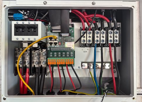
Terminate the supply leads to the motor contactor following the wiring diagram on the inside of the junction-box cover; three-phase machines must be rotation-checked before any bar is loaded. Power on for 2 seconds, observe the blade-housing fan or coupling direction, then power off — the cutting stroke must drive the movable blade downward against the fixed blade, never in reverse [S1].
Reverse rotation on a three-phase unit is corrected by swapping any two of the three phase conductors at the disconnect; do not attempt to re-phase at the motor terminal block without locking out the upstream breaker. A no-load run of 30 cycles confirms contactor pull-in, thermal-overload setting, and emergency-stop response before any bar is fed.
Blade Selection, Replacement, and Edge Geometry
Blade sets are model-specific and must be replaced as a matched pair, never as a single blade. The B&C TYC-HD19A takes a #6 (3/4") set (SKU BNC19), the TYC-NHD25 a #8 (1") set (SKU BNC25), and the BN Products DC-32WH takes a #10 (1-1/4") set priced at $129.00 for the matched pair [S3]. Edwards No. 15 blades (SKU EDW15) are sold separately from mounting hardware at $8.95–$140.00 depending on configuration [S3].
Mounting hardware is included with most B&C, BN Products, and EZE BEND sets, but Eagle Systems EAG6F and EAG6M replacement blades ship without hardware and require re-use of the original bolts, torqued to the OEM value to avoid jaw-spread under load [S3]. The TCO lens on consumables is covered in a 2026 rebar bender total-cost breakdown that quantifies blade spend as one of the five dominant 5-year cost lines on a rebar workstation.
Acceptance Test: No-Load, Single-Cut, and Continuous Duty
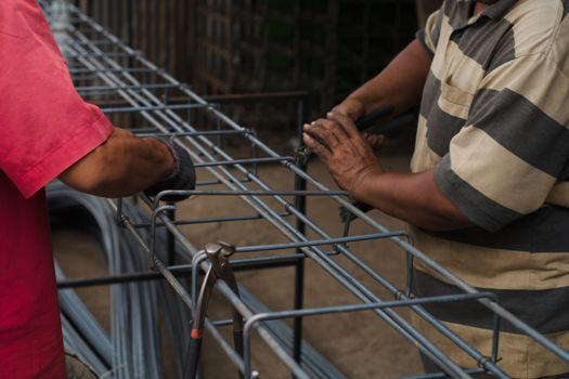
Three staged checks gate the machine into production service. Stage 1 is a 30-cycle no-load run confirming rotation, contactor engagement, and thermal-overload stability at ambient. Stage 2 is a single-cut test on the heaviest rebar grade the machine will see — the cut end should be square within 2° and free of burrs longer than 2 mm [S3].
Stage 3 is a 10-minute continuous-duty run at the rated cycle rate, monitoring motor current against the nameplate FLA. Sustained current above the FLA plate is a red flag pointing to dull blades, mis-set anvil clearance, or undersized supply wiring [S1]. A passing test clears the machine for site issue; a failing test blocks commissioning and routes the unit to a service bay.
Common First-Week Failures and Decision Triggers
Symptom-to-cause mapping shortens downtime in the first week. Burrs on every cut end mean blade-to-anvil gap is too wide; reset to the chart value or replace if edge chipping is visible. Motor overload trips under no-load point to wrong rotation, seized linkage, or undersized supply cabling. Hydraulic-style cutters that drift on the down-stroke have a failed seal or low hydraulic fluid, not an electrical fault [S1].
Replace, do not repair, any blade with a chip longer than 3 mm or with edge rounding that prevents clean rebar entry. Replace, do not adjust, any anvil with a mushroomed face — regrinding changes the geometry and invalidates the cut-capacity chart. Escalate to the OEM service channel when a 32–42 mm machine trips on thermal overload within the first 10 cuts, since the root cause is usually electrical, not mechanical, and field strip-down voids the warranty in most cases [S1].
Documentation, Spare-Parts Staging, and Handover
Close out commissioning with three records: a torque-verification log for every anchor bolt, a rotation-check sign-off with the date and electrician's name, and a blade-set SKU list cross-referenced to the cut-capacity chart. Keep at least one spare matched blade set per cutter on the site shelf for the 25 mm and larger classes — the lead time on a special-order set breaks the rebar-fab cycle, while shelf-stock blades restore the machine within an hour [S1][S3].
Trackable signals worth monitoring over the next quarter: a 10–15% drop in cut-end quality after 8,000–12,000 cycles is the normal blade-replacement trigger on mid-size machines; spiking that interval to under 5,000 cycles points to rebar grade mismatch, usually unannounced substitution from Grade 60 to Grade 75 stock on the project. Process engineers reviewing steel-strand installation practice on the same site can apply the same staged-acceptance and torque-log discipline to their prestressing hardware for consistent commissioning evidence across rebar and strand workflows.
Component reference pages worth checking: rebar cutter, linear guide, and crossed roller guide.