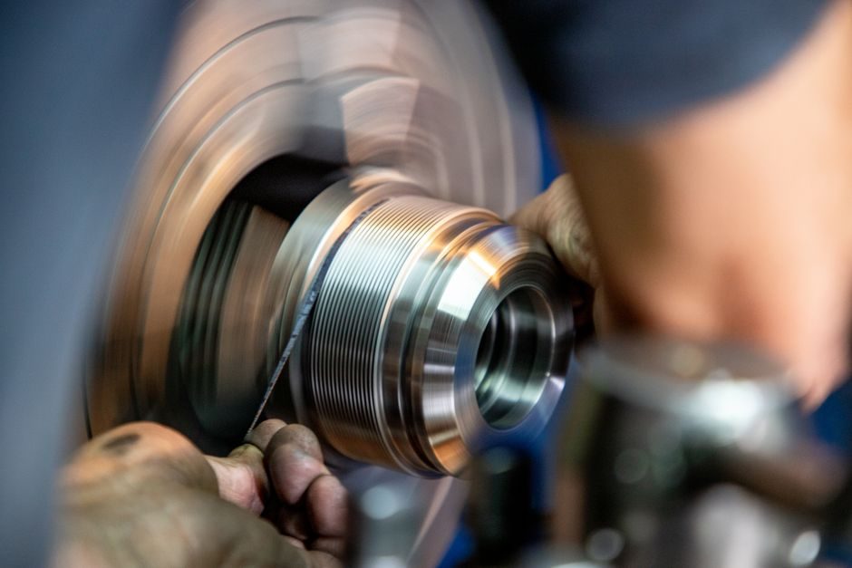
A retaining ring only performs its axial-positioning job if the groove is machined to the ring's published dimensional window and the ring is installed with the correct plier or applicator — external rings are radially contracted into a shaft groove, while internal rings are radially expanded into a bore groove using matched tip geometry [S1][S6].
This guide consolidates the 2026 reference data for retaining ring selection and installation: groove fit per DIN 471 (external/shaft) and DIN 472 (internal/bore), tooling choices for Smalley Spirolox spiral-wound rings versus stamped snap rings, hardness expectations (typically 44–51 HRC for spring-steel variants), and the failure signatures that force a re-spec rather than a re-install.
Ring Types and Direction of Installation Force
External retaining rings (also called shaft rings or "external snap rings") are installed by squeezing the ring ears with snap-ring pliers so the diameter *decreases* enough to pass over the shaft and snap into the groove; the design intent is that the relaxed free diameter is *smaller* than the shaft diameter, so the ring grips the shaft by residual elastic stress [S1].
Internal retaining rings ("bore rings") work in mirror image: pliers expand the ears outward, the free diameter is *larger* than the bore, and the ring seats against the bore groove shoulder. Spiral-wound retaining rings such as the Spirolox family from Smalley install without ears — a single-layer or multi-turn coil is wound into the groove using a special mandrel or hand-tool that does not require radial squeezing of the ring body [S4]. This makes spiral rings preferable where the shaft has a cross-hole, keyway, or undercut that would prevent a stamped snap ring from seating flat.
Groove Geometry: DIN 471, DIN 472, and ANSI B27.7 Windows
For metric shaft applications, DIN 471 defines the groove diameter, width, and edge-distance tolerances for external rings; DIN 472 covers the internal/bore equivalent. A practical rule is that the groove diameter sits below the shaft nominal (external) or above the bore nominal (internal) by a tabulated clearance, and the groove width must accommodate the ring's radial cross-section plus a small assembly clearance — typically 0.05–0.15 mm per side for rings under 50 mm shaft diameter. [S4]
ANSI B27.7 governs the inch-based snap-ring series (the "500" external and "510" internal series are common); published groove widths are typically the ring thickness + 0.005"/0.010" (0.13–0.25 mm) to allow plier-tip clearance during installation. Before any axial load is applied, the machinist should verify three numbers with a groove gauge or pin gauge: groove diameter, groove width, and edge distance from the shaft end — the last is critical because a ring that sits too close to the shaft end can "pop out" under thrust, while one set too deep leaves excessive cantilever [S1][S6].
Tooling: Pliers, Applicators, and Spirolox Mandrels

Standard snap-ring pliers come in two tip geometries: straight tips for through-shaft access and 90° angled tips for blind bores where the shaft shoulder blocks axial plier approach. Smalley publishes a Spirolox Retaining Ring Tooling Guide covering internal and external assembly tools in both inch and metric sizes, plus custom mandrel options for high-volume production [S4]. For exhaust-pipe and similar automotive service, dedicated single-purpose tools such as the JIMS 747 exhaust-pipe retaining-ring installer exist — these align the ring and the groove in a single motion and prevent the over-spreading that cracks stamped rings during hand installation [S5].
The most common installation error is over-spreading (internal) or over-compressing (external) the ring ears beyond the elastic limit; this permanently yields the material so the ring no longer grips, and the only remedy is replacement. A secondary error is using pliers whose tip diameter is too small for the ring's ear holes — the tips punch through the hole edge and deform the ear, again destroying the spring-back. For Smalley Spirolox rings, the assembly tool winds the ring into the groove tang-by-tang; the operator should never try to "snap" a spiral ring into place the way a stamped ring is installed, because the coiled end will unwind past the groove and the ring will not seat.
Material, Hardness, and Surface Treatment
Standard carbon-steel retaining rings (e.g. Smalley standard series, DIN 471 spring steel) are typically supplied at 44–51 HRC after heat treatment, with a phosphate-and-oil (P&O) or black-oxide finish for corrosion resistance during storage. The Sogou technical entry for shaft retaining rings ("轴用弹性挡圈") lists three production acceptance criteria: surface flatness, hardness/elasticity within the published band, and the absence of edge burrs — any of these three failing the incoming inspection disqualifies the lot before it reaches the assembly line [S6].
For stainless variants, AISI 302 and 17-7PH are the common choices; 17-7PH allows higher strength at temperature but costs roughly 3–5× the standard carbon-steel ring. Where the application sees cryogenic temperatures or hydrogen-embrittlement risk (turbo-generator end-winding retaining rings, for instance), non-magnetic austenitic or Inconel variants are specified — the GlobalSpec product index for Turbo Generator Retaining Rings confirms this is a distinct sub-category with its own metallurgical qualification chain [S1]. Plated rings (zinc, cadmium) are sometimes seen in legacy specs, but cadmium-plated rings are restricted under RoHS-style substance rules in many regions, so verify compliance before specifying.
Failure Modes: Symptom → Root Cause → Corrective Action
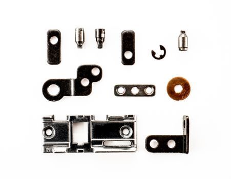
<b>Symptom 1 — ring "pops out" of the groove under axial load.</b> Root cause: groove diameter is too close to the shaft nominal (external) or too close to the bore nominal (internal), so there is no clearance shoulder for the ring to react against; alternatively, the edge distance from the shaft end is too short and the ring rides up the chamfer. Corrective action: re-cut the groove to the DIN 471/472 or ANSI B27.7 tabulated value, or upsize the shaft shoulder. <b>Acceptance test:</b> push the assembled ring against the shoulder with a known thrust (typically 5–10× the design axial load) and check for axial creep with a dial indicator. [S4]
<b>Symptom 2 — ring does not seat flat, "rocks" in the groove, or sits cocked.</b> Root cause: groove width is too wide, allowing the ring to tilt under radial load, or the groove has a burr on one edge that lifts the ring body. Corrective action: measure groove width with a tapered gauge; if it exceeds the published maximum, the part is scrap or the groove must be re-machined. Deburr the groove edges with a hand stone before re-install. <b>Do not</b> try to "peen" the groove edges down — this work-hardens the surface and changes the hardness band, which can crack the next ring installed.
<b>Symptom 3 — ring ears break during or after installation.</b> Root cause: over-spreading (internal) or over-compressing (external) during plier use, or material defect (out-of-band hardness, decarburization). Corrective action: replace the ring; inspect the plier tip diameter and confirm it matches the ring's ear-hole diameter. If failures repeat, sample the lot for hardness and microstructure — a single failed ear usually indicates installer error, a pattern of failures across a batch points to a heat-treat or material lot issue [S6].
When to Repair vs Replace vs Re-Spec
If the ring is intact and the groove is within tolerance, the assembly is serviceable — re-use is normal. If the ring shows any plastic deformation (gap between ears has changed from the as-shipped value, ring has lost roundness, or a tang has lifted on a Spirolox), replace the ring; do not re-install a deformed ring. If the groove is out of tolerance, the decision splits: replace the part (preferred for low-volume or safety-critical assemblies) or re-machine the groove (acceptable for high-value shafts such as turbo-generator rotor ends, where the slewing ring bearing and retaining-ring stack is a matched set qualified as a unit) [S1].
For new designs, re-spec to a spiral-wound ring when (a) the shaft has features a stamped ring cannot clear, (b) the assembly sees high rotation speed where a stamped ring's ear holes become stress concentrations, or (c) the groove is too shallow for a thick-section stamped ring — Spirolox cross-sections start around 0.4 mm and can therefore fit tighter axial envelopes than comparable stamped rings [S4]. For bore-side retention where the surrounding hardware is a linear guide carriage or a crossed-roller guide end-cap, verify that the ring's outer diameter does not interfere with the rail's end-seal groove before finalising the spec.
Cross-Reference: O-Ring Backup vs Retaining Ring Function

Engineers sometimes conflate retaining rings with O-ring backup rings or pressure transmitter gland hardware — the functional intent is different. A retaining ring locates a component axially against a shoulder and reacts only hoop stress plus axial thrust; an O-ring seals a static or dynamic interface and reacts radial compression. Selecting the wrong part leads to either a seal that does not retain the shaft, or a ring that does not seal the fluid. For assemblies that need both functions — a sealed and axially-located bearing insert, for example — the retaining ring sits in its own groove external to the seal gland, and the two are verified independently. [S1]
Trackable signal for 2026 sourcing: lead times on DIN 471/472 metric spring-steel rings from European mills remain in the 6–10 week band for non-stock sizes, while Smalley Spirolox equivalents in standard 300-series and 400-series stainless are typically ex-stock US in sizes up to ~300 mm bore. If a draw calls for a non-standard groove diameter, plan a custom-tooling lead time of 10–14 weeks for the dedicated Spirolox applicator [S4].
Related analysis: Galvanized Sheet Supply Chain 2026: Specs, Pricing, and Sourcing Signals.