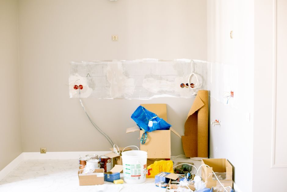
Rigid insulation board installation on concrete and masonry walls, the underside of floor slabs, and perimeter/under-slab locations follows the four-stage UFGS-07 21 13 acceptance pattern of substrate preparation, fastening, continuity, and protection [S2].
Spec writers select a board family first (XPS, EPS, polyiso, mineral wool) against substrate, exposure, fire rating, and required R-value per inch, then lock the install method — adhesive-bonded versus mechanically fastened — to substrate type and service environment [S2][S3].
Substrate Preparation and Pre-Install Verification
Substrate must be clean, dry, and free of bond-breaking contaminants before any board is set; UFGS-07 21 13 Part 3.2 lists preparation, blocking around heat-producing devices, and existing-conditions verification as mandatory pre-install steps on every project [S2].
Two checks gate the rest of the work: (1) confirm the design R-value, board thickness, and density match the drawings; (2) confirm substrate moisture is below the adhesive manufacturer's published limit — wet concrete or masonry is the most common cause of failed board adhesion and rework. Existing wall penetrations, conduits, and dissimilar-material transitions must be blocked or shimmed so the board sits on a flat plane, since a 3 mm gap under a 50 mm board creates a cold bridge roughly proportional to the unfilled area [S2].
Adhesive-Bonded Versus Mechanically Fastened: Criteria Comparison
For concrete and masonry walls, UFGS-07 21 13 Sections 3.4.3 and 3.4.4 separate the two accepted attachment methods, and the right pick depends on substrate, exposure, and fire rating [S2].
Adhesive attachment (3.4.3) suits interior dry walls, retrofit over cured concrete, and projects where penetrating fasteners risk hitting rebar or embedded services. Mechanically fastened attachment (3.4.4) is required for exterior exposure, below-grade, and any assembly carrying a fire-resistance rating that depends on the fastener spacing. Under-slab and perimeter work typically combines both: full-coverage adhesive plus supplementary mechanical fasteners at edges and penetrations, per Sections 3.5.1, 3.5.2, and 3.6.2. Wall furring strips (3.4.1) are an alternative where the finish cladding needs a drained/vented gap, but they add depth and must be accounted for in the door and window reveal dimensions. Project context for fast-tool installation practice on adjacent equipment — such as a rebar straightener on site prep and anchoring — reinforces that the same substrate-readiness discipline governs every anchored install on a slab.
Walls: Concrete, Masonry, and Furring-Strip Patterns
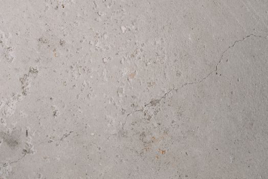
On concrete and masonry walls, boards are typically applied in a running-bond pattern with tightly butted joints, edges bearing on continuous substrate, and staggered vertical seams between courses — UFGS-07 21 13 specifies board-type insulation for these substrates because blanket and loose-fill cannot hold dimensional tolerance on a vertical plane [S2].
Adhesive is applied in vertical beads or full-coverage trowel pattern per the adhesive manufacturer's coverage rate; boards are then pressed into place and held until initial grab. Mechanically fastened assemblies use corrosion-resistant fasteners — typically powder-actuated or pre-drilled with a washer plate — at a spacing matched to the board manufacturer's wind/seismic load table, generally 300-400 mm on centre in the field and 200 mm at edges and openings. Joints are sealed with compatible pressure-sensitive tape (UFGS-07 21 13 Section 2.3) to maintain the continuous thermal envelope; gaps at penetrations are filled with expanding foam or mineral wool batt, never left open. For complex envelope geometry, the industrial blower selection guide frames how airflow and pressure losses stack up in conditioned spaces — a useful parallel when judging whether an imperfectly sealed envelope is actually leaking conditioned air or just thermal energy.
Underside of Concrete Floor Slabs and Perimeter/Under-Slab
Below-slab and underside-of-slab work follows Sections 3.5 and 3.6 of UFGS-07 21 13: a single layer of board is applied direct to the structural surface, then protected by a protection board or coating where the assembly is exposed to mechanical damage or UV [S2].
On the underside of a concrete floor slab, mechanical fastening (3.5.1) is the default because gravity loads the bond line in shear for the life of the building; adhesive-only systems (3.5.2) are limited to accessible dry interior zones with positive substrate prep. Perimeter and under-slab (3.6) requires the manufacturer's installation instructions to govern edge detail, vertical leg height, and protection from backfill — typically a protection board or rigid coating above the foam where the slab edge is exposed. UFGS-07 21 13 also separates vapour retarder placement by assembly: frame walls and roofs (2.2.1), masonry cavity walls (2.2.2), and under-slab (2.2.3) each have a specified location for the retarder relative to the board, and getting this side of the detail wrong is the most common cause of interstitial condensation in cold climates. Real-world project sequencing — analogous to the spec-first thinking in this induction furnace installation field guide — rewards lining up trades so vapour retarder, board, and protection layer are all installed in a single continuous pass.
Joint Continuity, Vapour Retarders, and Fire/Safety Details
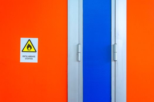
Continuity of insulation (UFGS-07 21 13 Section 3.3.4) and the cold-climate requirement (3.3.3) are the two non-negotiable checks: boards must wrap the envelope without thermal bridges at slab edges, window perimeters, and roof-to-wall transitions, and the assembly's thermal performance is only as good as its weakest joint [S2].
The vapour retarder sits on the warm side of the insulation in cold climates and follows the location specified in 2.2.1-2.2.3 for each assembly; laps are sealed with pressure-sensitive tape (2.3) and the assembly is terminated into access panels and doors (3.8) so serviceable items remain serviceable. Fire protection is governed by 2.1.2 — the specified fire rating drives both board family (mineral wool versus foam) and whether a protection board or coating is required on the exposed face. Prohibited materials (2.1.6) explicitly block the wrong foam grade in fire-rated assemblies. During install, Section 1.5 calls for respiratory protection when cutting fibrous board and for blocking heat-producing devices (3.2.1) so insulation cannot contact recessed lights, transformers, or flue chases — a frequent cause of field rework. Reference: the insulation board encyclopedia entry consolidates these substrate and material constraints.
Acceptance Criteria and When to Reject the Work
Acceptance is a documented checklist, not a visual pass: verify board type and density against the submittal, confirm fastener type/spacing/embedment against the fastener schedule, and confirm vapour retarder lap continuity with no punctures larger than 6 mm unsealed [S2].
Reject and replace if any of the following appear: board joints gapped more than 3 mm, adhesive starved (less than 80% contact when a board is pulled), fastener heads penetrating the board face, vapour retarder tears at corners, or any board in contact with a heat-producing device without a clearance block. Substrate-side, EPS and XPS boards must be protected from solvent-based adhesives and direct sunlight during storage (Section 1.4) — both degrade the skin and reduce bond strength on the wall. For dense-foam retrofit over existing masonry where the wall is unknown, pre-drilling a test fastener is the cheapest insurance against hitting live services; for cold-storage or freezer rooms, follow the cold-climate requirement (3.3.3) and add a continuous air/vapour seal on the warm side before closing the wall. Adjacent trades, like the structural choices laid out in this tool steel selection guide, share the same "right grade for the service environment" logic: the cheapest board on the bid sheet is rarely the cheapest board in service. EPS-board retrofits on existing masonry often use a polyurethane insulation tie-in at penetrations because the two foam families seal against each other reliably when joint geometry is tight.
Trackable next signal: when a project mixes above-grade and under-slab boards, confirm the under-slab side carries a protection board or coating per 2.4 before backfill is scheduled — backfill scheduled before protection-board inspection is the single most common cause of foam damage in residential and light-commercial foundations.
Spec-level background on the components involved: linear guide.