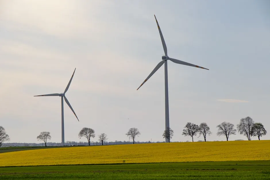
Wind turbine rotor-shaft and gearbox bearing selection is driven by 20-year L10 life targets, ISO 281-adjusted dynamic load ratings, and a lubricant cleanliness ceiling of ISO 4406 18/16/13 or cleaner for main-shaft and high-speed gearbox stages, per current bearing selection practice [S4].
The main-shaft, main-shaft trunnion, gearbox planetary, gearbox HSS (high-speed shaft), generator, yaw, and pitch drives each demand a different bearing type, and the right call is set by combined radial/axial load ratio, misalignment tolerance, and DN limit, not by brand alone [S3].
Which bearing type fits each wind-turbine position
Spherical roller bearings are the default for the main-shaft and the main-shaft-to-carrier trunnion because they tolerate 0.5-2° static misalignment from frame deflection and carry the rotor's combined radial+thrust load in a single unit, making them the most-installed rotor bearing type across the 1.5-8 MW class per roller bearing selection references [S2][S3].
Tapered roller bearings are the standard for the gearbox planetary stage (pinion/carrier), HSS, and intermediate gear stages where combined radial+axial load is high and misalignment is small (typically less than 0.001 rad), and they are typically paired back-to-back or face-to-face per tapered roller bearing engineering notes from major suppliers [S2][S3].
Cylindrical roller bearings (full-complement or cage-guided) are used on the gearbox intermediate shaft where radial load dominates and axial load is carried by a separate thrust position, while deep-groove and angular-contact ball bearings are limited to the generator, yaw, and pitch drives where loads are lower and speed is higher.
Load case, L10 life, and the 20-year design target
Wind-turbine rotor bearings must deliver a calculated L10h life of at least 175,200 hours, the 20-year continuous service benchmark that ISO 281:2007 / ISO 76 dynamic load rating math is benchmarked against, and a derated application factor (a1 through a3) per [S4] is applied to absorb load variability from gusts, yaw transients, and emergency stops.
The non-rotor stages (yaw, pitch, generator) accept a much shorter design horizon, typically 50,000-100,000 h L10h, because maintenance access is crane-friendly, while the main-shaft trunnion and gearbox HSS are the lifetime-limiting positions and drive bearing size, steel cleanliness (vacuum-degassed ASTM E45-rated steel), and raceway super-finish selection per [S4].
White-etching cracking (WEC) and axial cracking from rolling-contact fatigue are the dominant failure modes, which is why specifiers are now selecting case-carburized steels with retained austenite windows in the 15-30% range and specifying surface-initiated fatigue resistance over subsurface-driven limits for new designs [S4].
Lubrication and oil cleanliness gates
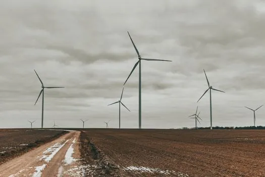
Main-shaft and gearbox bearing sumps in modern multi-MW turbines target ISO 4406:1999 cleanliness codes of 18/16/13 (5-15 µm particle count) for the bearing-inlet oil, and 16/14/11 is now the practical target for HSS and PCD (planetary-carrier-disc) positions where filtration is generous and oil volume is small [S4].
Grease-lubricated positions (yaw, pitch, generator) target NLGI Grade 2 with a base-oil viscosity of ISO VG 100-460 depending on the dN number, and a relubrication interval based on the elapsed-time and rpm product rather than calendar months, which is the standard practice on roller bearing service guides used by OEMs [S2][S3].
Forced-oil jets at the main-shaft trunnion carry a nozzle flow rate set at 0.5-1.5 L/min per jet and an inlet temperature controlled to 50-65 °C, which keeps the lubricant film parameter κ in the 1.5-3.0 range at full load and limits the risk of skidding during low-speed startup [S4].
Clearance, fits, and mounting per DIN 620
Main-shaft spherical roller bearings are typically supplied in C3 or C4 internal clearance groups per DIN 620 Pt 4 to compensate for thermal expansion of the steel shaft in operation, and the shaft/housing fits are chosen so the ring most likely to expand (usually the inner) is mounted with a tight transition fit, often a loose-pressing h6 or js6 on the shaft, per [S4].
Planetary-stage tapered roller bearings are normally supplied in C2 or CN clearance groups with a heavier press fit on the cone (typically m6 or k6) and a loose fit on the cup (typically H7 or J7), so thermal growth of the pinion shaft does not preload the bearing once steady-state temperature is reached.
Housings for main-shaft sphericals are typically cast iron EN-GJS-400 or EN-GJS-500 per EN 1563, with a bore tolerance of H7 or H8 depending on whether the bearing OD is the floating or locating ring of the arrangement, per [S3] design guides.
Failure modes and condition-monitoring signals

The five classes of bearing damage that show up in wind-turbine drivetrains are spalling from rolling-contact fatigue, axial cracking from WEC, smearing from lubricant starvation, cage fracture from vibration, and electrical-erosion pitting from VFD-induced shaft currents that bypass the bearing through the gearbox, with the latter now a recognized failure mode on DFIG and full-converter turbines [S3][S4].
Condition-monitoring gates for wind farms in 2026 include a combination of CMS vibration (4-8 kHz envelope bands), AE (acoustic emission) sensors on main-shaft trunnion and HSS, oil-debris ferrography (target less than 30 ppm Fe per L at HSS outlet), and on-line ISO 4406 particle counters on the main lube loop, all feeding the SCADA system at a sampling rate of 1 Hz or higher for trend tracking [S4].
Insulation rings on the gearbox HSS and PE (potential equalization) brushes on the rotor shaft have become near-default for any new turbine above 3 MW because VFD common-mode voltage routinely exceeds 20 V peak on the rotor-circuit cable run, and without PE the bearing inner race picks up a discharge current in the 0.5-5 A range that drills a washboard pattern into the raceway [S4].
Comparison of bearing options for wind-turbine drivetrains
On four decision criteria, the four most common options for wind-turbine drivetrain positions line up as follows: a spherical roller bearing carries 100% combined radial+thrust load and tolerates 0.5-2° misalignment but is speed-limited by a dN ceiling of around 300,000 mm·rpm; a tapered roller bearing carries 100% combined load with a misalignment tolerance of only 0.001-0.002 rad and a dN ceiling of around 450,000 mm·rpm, so it is faster but stiffer; a cylindrical roller bearing carries pure radial load with the highest dN ceiling (up to 1,500,000 mm·rpm for full-complement designs) but needs a separate thrust position; a deep-groove ball bearing carries light combined load with the highest dN ceiling and the lowest friction torque but the shortest L10h life at heavy load, which makes it the wrong pick for the rotor and the right pick for the yaw and pitch [S2][S3].
On cost-per-MW, spherical rollers are the most expensive per unit (a 22328 CC/W33 main-shaft bearing typically lists 4-8× the price of a similarly-sized deep-groove ball), while cylindrical and deep-groove are the lowest, which is why specifiers place each bearing type only where its load/speed/misalignment profile is genuinely needed, per the [S3] selection guide.
Supplier map and 2026 sourcing notes

The wind-turbine main-shaft spherical roller bearing supply base in 2026 is concentrated among a small group of multi-product bearing houses; Wuxi Spark Bearing Co., Ltd. (China) lists the WSBC 23028 CA/W33 and WSBC 24024-2CS spherical roller series as main-shaft and trunnion candidates in their public catalogue [S2], and American Roller Bearing Company (US) lists Cylindrical, Tapered, and Spherical Roller lines for power-generation and metal-rolling drivetrains in their published product range [S3].
For wind farms replacing failed or near-end-of-life main-shaft bearings, the practical sourcing path is to (1) send the failed bearing's data plate plus a damage photo set to a custom-bearings shop like American Roller Bearing's bearing-modification service, (2) match the 23028/24024/24124 bore series to the rotor hub bore, and (3) request an L10h calculation per ISO 281 with the wind farm's site-specific Weibull shape factor, per [S4] and [S3].
For specifiers comparing the wind main-shaft decision to other drivetrain classes, the related reference on mining roller bearing selection applies the same L10h and ISO 4406 gates to a far harsher dust/load environment, and the material-handling bearing spec map is a useful contrast for lower-rotation-speed, higher-shock applications.
For packaging-line and conveyor drivetrains adjacent to wind applications, the packaging-line roller bearing spec map shows where sealed deep-groove ball bearings replace greaseable sphericals as the maintenance burden shifts, while the roller conveyor page covers the low-speed idler-end of the spectrum where tapered and ball bearings share the duty cycle.
Trackable signals to watch in the next 6 months: (1) any revised ISO 281:2007 amendment on lubrication film parameter κ for slow-speed main shafts, (2) extension of the WSBC 240xx and WSBC 241xx series catalogue by Wuxi Spark Bearing with bigger-bore 24128-24136 parts for 6-8 MW turbines [S2], and (3) any move by American Roller Bearing to publish a wind-specific datasheet on PE-brushed HSS sphericals [S3].