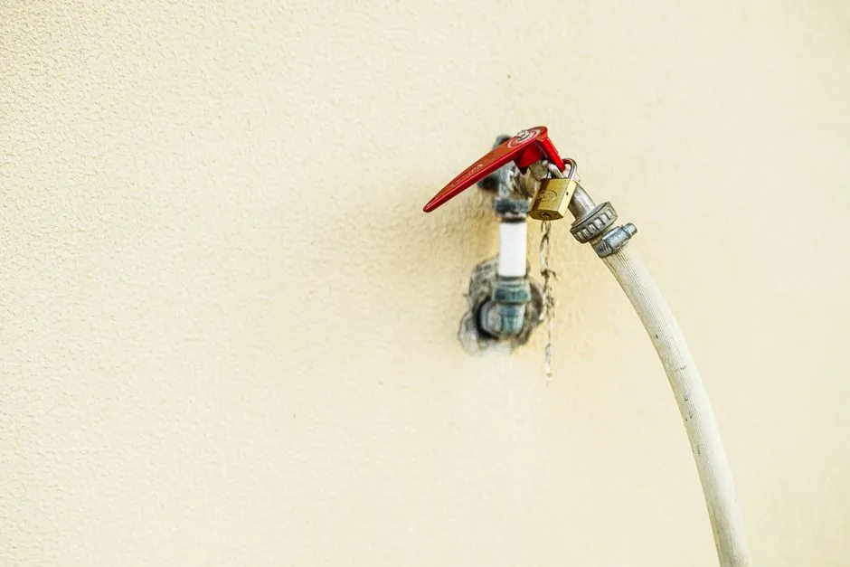
A safety relief valve must open at a predetermined pressure, relieve rated capacity, and close after the protected system returns to a safe pressure [S1][S2].
For irrigation, selection must cover pump or boiler overpressure, water hammer, thermal expansion, blocked outlets, valve-failure cases, discharge routing, and the applicable system code [S1][S7].
Define the Overpressure Cases Before Choosing a Valve
A pressure relief valve protects vessels, piping, and other equipment from pressure above the design pressure or maximum allowable working pressure by a fixed, predetermined amount [S1][S2]. It is an emergency device, not a pressure-control valve, and it does not regulate irrigation operating pressure [S1].
Prepare a credible overpressure inventory before selecting the valve. The cases include a stopped or failed pump, a blocked irrigation-main outlet, control-valve failure, hose or tube rupture, thermal expansion in a blocked section, fire exposure, and pressure transients [S1][S7]. Calculate the required relieving capacity from the governing case, not from nominal pump flow alone [S1][S7].
For irrigation hydraulics, include the maximum working pressure of the weakest protected component, the pump or boiler relief characteristic, the water-hammer transient, and the back pressure that will exist at the valve discharge [S1][S2]. The valve must still operate during a power failure, with process fluid as its energy source [S1].
Match the Valve Action to the Protection Duty
Safety relief valves are pop-off, fast-acting devices suited to sudden pressure spikes, while conventional relief valves open progressively and can remain partly open [S2][S3]. Thermal relief valves are a different class, intended to discharge a very small quantity caused by thermal expansion [S3].
Use a safety or pressure safety valve when the protected system can suffer a rapid pressure rise and the device must open promptly at the set pressure. Use a conventional pressure relief valve where the installation requires controlled or proportional opening and partial relief [S2]. Do not substitute a thermal expansion valve for a high-capacity overpressure case: its design point is small expansion flow, not pump or boiler capacity [S3].
Spring-loaded pressure relief valves are available from an irrigation-supplies retailer [S5]. That range describes one commercial product, not a universal engineering selection rule.
Compare Set Pressure, Capacity, and Operating Limits
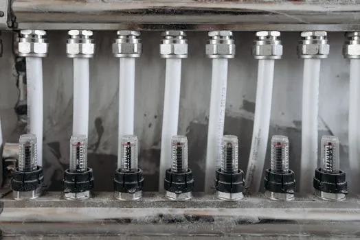
Set pressure, allowable overpressure, back pressure, and relieving capacity are the four core inputs to overpressure protection [S2]. The selected valve must satisfy both its set-pressure requirement and its rated discharge at the specified allowable overpressure [S1][S2].
Do not select on inlet size alone. Capacity depends on the valve characteristics, set pressure, inlet and outlet pressure loss, fluid properties, and back pressure, so sizing must follow the applicable pressure-relieving calculation method [S1][S7]. The irrigation main must not be allowed to defeat the rated discharge through excessive back pressure.
Choose Materials and Configuration for Water Service
The valve construction must be compatible with the protected fluid and must operate smoothly across the water conditions expected in the system [S1][S2]. Irrigation service also exposes wetted components to sediment, fertilizer, chlorine, and variable water chemistry, so material selection must consider the actual service fluid rather than assume clear, potable water [S1][S6].
Evaluate the valve body, trim, seat, and closure materials as one set. Select a configuration that isolates moving parts from corrosion where required and that can be inspected and serviced without compromising the set pressure [S1][S6]. The closure and seat arrangement must provide repeatable opening and tight shutoff after the pressure returns to a safe level [S1].
Size the inlet and discharge piping so they do not create a capacity limitation greater than the valve itself. Installation details, including inlet and outlet geometry and abrupt pressure fluctuations, can affect valve behavior [S2]. Debris-flushing provisions are valuable where irrigation water contains sediment, because lodged material can affect lift, seating, or closure [S4].
Apply Code and Manufacturer Constraints by System Type
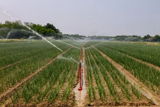
Selection, sizing, manufacture, assembly, test, installation, and maintenance all contribute to the protection provided by a pressure relief valve [S1]. The engineering basis should be consistent with ASME Section VIII, Division 1, and API 520 where those documents govern the protected pressure equipment and relief-device design [S1].
A fire-sprinkler installation is a different code case. NFPA 13 requires a listed relief valve of at least 1/2 inch for wet-pipe systems, operating at 175 psi or 10 psi above maximum system pressure, whichever is greater; an auxiliary air reservoir is an exception [S4]. For that application, select a factory-set, listed valve meeting the applicable UL or FM requirements [S4].
These values apply to that fire-sprinkler selection context and should not be transferred to an unrelated irrigation code basis. Irrigation fire-protection systems require their own code and listing review.
Install, Inspect, and Test the Selected Valve
The protected system can be damaged during installation if a relief valve is isolated against a hydrostatic test and later left closed. In fire-sprinkler service, listed valves designed for temporary isolation during hydrostatic testing should be reopened and returned to service [S4].
Verify set pressure, seat tightness, and relieving capacity before commissioning. Record the identification number, set pressure, rated capacity, fluid, materials, and installation orientation. The test interval should follow the governing code, manufacturer instructions, and service conditions, because irrigation systems may encounter seasonal operation, sediment, fertilizer exposure, and thermal expansion [S1][S6].
Inspect for debris, corrosion, damaged seats, leakage, and restricted piping. A valve that leaks at operating pressure, chatters, fails to reseat, or cannot demonstrate rated discharge is not fit for service [S1][S4].
Identify the Correct User and Exclude the Wrong Equipment
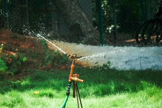
The appropriate user is a designer or owner responsible for a defined overpressure case, a known water property, a selected discharge route, and an applicable code basis [S1][S7]. The same discipline applies when selecting an air release valve for a separate trapped-air problem, but an air-release valve does not replace a high-capacity safety relief valve.
The mainstream irrigation pressure regulator or control valve is not a substitute for a safety relief valve. It is intended to regulate pressure, not to provide emergency relief at a set pressure under failed controls, blocked outlets, or thermal events [S1]. Similarly, an automatic recirculation valve may manage pump recirculation but does not discharge an overpressure event from the protected system.
Do not specify a commercial adjustable irrigation valve from a catalog price or advertised range alone. The selection file must record the governing overpressure, calculated capacity, allowable overpressure, back pressure, set pressure, fluid temperature and chemistry, wetted materials, inlet and outlet losses, code route, test method, and maintenance owner [S1][S5][S7].
Before purchase, compare the proposed valve against the protected equipment limit, governing emergency case, calculated relieving capacity, and system code. Reject the selection if any of those four checks cannot be demonstrated in writing.