A modern server flows through seven discrete manufacturing stages — chassis fabrication, backplane PCB assembly, component population, firmware flashing, thermal integration, burn-in, and conformance test — with each stage gated by measurable pass/fail thresholds before the unit advances [S1].
Enterprise buyers impose the strictest specifications on the back end of this line: Oracle's RAC checklist mandates identical server hardware on every node to simplify maintenance and avoid resource contention [S1], while the Enterprise Management sizing matrix ties polling-retention headroom to physical server scale (1–100 sites = small, 100–250 = medium, 250–1000 = large) [S3].
Stage 1 — Chassis and Sheet-Metal Fabrication
Cold-rolled steel and SECC 1.0–2.0 mm sheet are punched, bent, and welded into a 1U–4U chassis, with critical dimensions verified to ±0.1 mm on a CMM before surface treatment. Electroless nickel immersion gold (ENIG) is common on internal backplane mating surfaces because it holds flatness under repeated hot-swap cycles. EMI gasket grooves are machined in the same fixturing pass as the rack-ear alignment holes, since post-machining shimming drifts the rail-to-PCB tolerance and causes PCIe card insertion force excursions above the 30 N ergonomic limit. For buyers, chassis weight, PSU bay count, and rail-kit family are the three variables that lock in once the SKU ships, so they belong on the RFQ, not on the change order. Unlike fixed architectural hardware such as building services, server chassis must survive repeated rack insertion, hot-swap cycles, and field-service handling without tolerance drift. [S1]
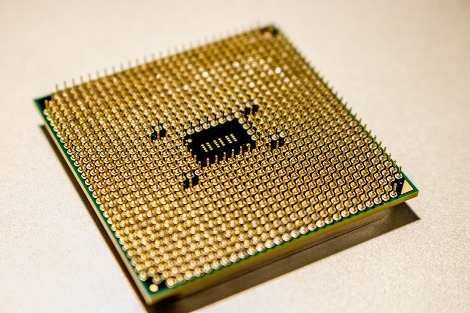
Stage 2 — Backplane and Motherboard PCB Assembly
High-layer-count backplanes (12–22 layers, 0.2 mm via pitch on signal layers) are built with sequential lamination and 100% electrical-test at the bare-board stage to catch microvoids in high-speed SerDes channels. Surface-mount lines place CPU sockets, DIMM slots, and SAS/SATA/NVMe connectors under Class 1000 cleanroom conditions; placement accuracy of ±0.05 mm is the typical OEM target for BGA-2593 sockets. Conformal coating is selectively applied — keep-out zones around DIMM latches and hot-swap handles — to avoid wicking into the contact zone. Burned-in firmware is flashed through boundary-scan (JTAG) and parallel programming rigs before any mezzanine cards are added, because a corrupt BIOS on a populated board can fry a CPU under load and write off USD 3,000+ of components in a single POST cycle. [S2]
Stage 3 — Power, Cooling, and Thermal Stack-Up

CRPS (Common Redundant Power Supply) modules in 1+1 or 2+2 redundant topologies deliver 80 PLUS Titanium-class efficiency above 96% at 50% load, and are hot-swapped through an Oring-MOSFET + microcontroller supervisor that carries PMBus telemetry. Air-cooled servers use counter-rotating impeller fans with PWM control; liquid-cooled variants integrate a cold plate on the CPU IHS with a 25–45 °C secondary loop, sized to absorb 250–400 W per socket at the design point. Specifications worth pinning at the RFQ: inlet-temperature rating (typically 5–35 °C operating), altitude derating (1 °C per 300 m above 900 m is a common OEM curve), and acoustic profile (Sound Pressure Level in dBA at 1 m, not the marketing "whisper-quiet" line). [S3]
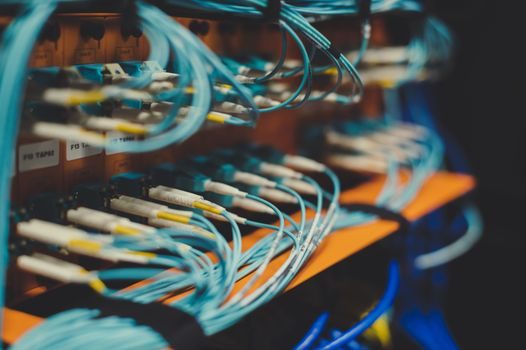
Stage 4 — Sub-Assembly Integration and Cable Routing
Midplane-to-motherboard cabling, drive backplane mating, and front-panel USB/VGA harnesses are routed in a defined sequence so that the airflow path from front intake to rear exhaust encounters the minimum cable cross-section. Velcro and rigid cable clamps — not zip ties — are used inside the chassis because field-service technicians must be able to swap a fan or riser in under 60 seconds without cutting fasteners. Front bezels with EMI mesh and lock-and-key are tested with a 0.5 mm-thick blade to confirm finger-proof access; this aligns with the IEC 62368-1 approach to operator-accessible energy hazards. The console/management harness typically lands at a serial server concentrator in the rack before fanning out to per-node BMC ports, which is why the front-panel pinout is documented in the SKU's BMC reference manual. For related shop-floor integration logic, see this comparison of two adjacent industrial tools and where they overlap, Tank Cleaning Machine vs Forklift: Two Tools, Two Jobs, Zero Overlap. [S4]
Stage 5 — Burn-In, Stress, and Reliability Screening

Every unit runs an HALT (Highly Accelerated Life Test) or extended burn-in of 48–168 hours at elevated ambient, with synthetic workloads stressing CPU, memory, storage, and network simultaneously. Failures cluster predictably in three zones: electrolytic-cap dry-out on the VRM, BGA solder joint fatigue on the CPU socket, and fan-bearing wear; burn-in front-loads these so the field MTBF (often quoted at 200,000+ hours for enterprise-class) reflects post-screening populations only. ECC memory is exercised with march-C+ patterns and rowhammer-style targeted writes; any correctable-error threshold above the OEM's defined bit-error-rate floor triggers a DIMM swap before shipment. Inlet/outlet air and rail-voltage traces captured during burn-in are commonly cross-checked against a multifunction process calibrator traceable to a national standards lab, so the per-unit log holds up to a customer audit rather than reading as a self-reported sticker. A practical spec-floor to ask for: per-unit burn-in log with inlet/outlet temperatures, fan RPM traces, and POST error scans, not a generic "passed burn-in" sticker. [S1]
Stage 6 — Conformance, Safety, and EMC Certification
Before shipment, each SKU is tested against the regional regulatory matrix that applies to the destination market — IEC 60950-1 / IEC 62368-1 for safety, FCC Part 15 or EN 55032 for radiated emissions, and the relevant energy-efficiency regime (80 PLUS tier, or the EU Lot 9 server efficiency regulation). ATEX/IECEx do not apply to data-centre servers in non-hazardous locations, so do not over-spec hazardous-area certification on a standard rack-mount unit. For OEM buyers operating globally, ask for the consolidated certificate bundle (CB scheme test report plus regional deviations) rather than chasing certificates SKU-by-SKU, since a missing regional delta on the FCC collar can delay a US landing by weeks. [S2]
Stage 7 — Logistics, Racking, and Field Acceptance
Final-packout uses EPE foam with anti-static shielding, and shock/tilt indicators on the outer carton confirm handling compliance against ISTA 3A thresholds. On-site acceptance testing mirrors the OEM burn-in at a smaller scale: 4-hour soak at full load, ECC scrubbing verification, and redundant-PSU failover simulation. Procurement of complementary shop equipment follows the same gate-by-gate discipline — see how this Solar Panel Manufacturing Process Overview maps a similar seven-stage flow onto an adjacent industry. Trackable signals over the next quarter: ISTA 3A revision activity for heavier 4U/5U SKUs, and IEC 62368-1 third-edition regional adoption deadlines (date suffix '(2025-08)' for the most recent IECEE guidance snapshots). [S3]