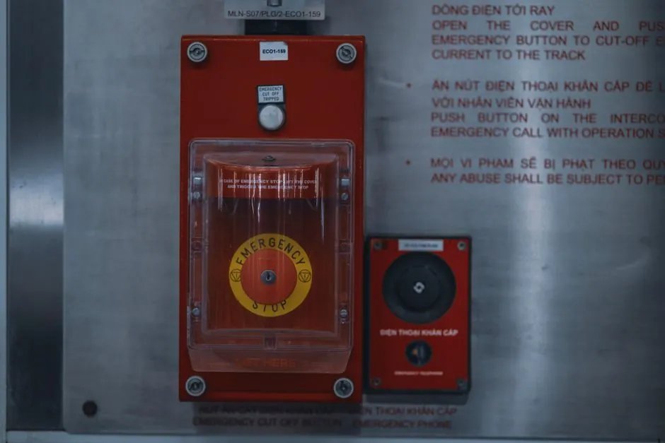
A 2-position or 3-position selector switch feeding a relay coil is the cheapest way to add electrical interlock to a manual/automatic, local/remote, or pump-1/pump-2 control scheme, because the switch only carries coil current while the DPDT or 3PDT relay contacts carry the load [S2][S4].
The pattern repeats across process plants: a rotary knob on the panel, a latching or spring-return detent behind it, a pair of contact blocks rated for 10 A at 250 VAC or 24 VDC, and one or two general-purpose relays (or a safety relay) that hold, drop out, and mutually exclude the competing outputs [S1][S2][S4].
Why a selector switch plus relay beats a direct-wired selector for interlock duty
A selector switch is actuated with a rotary knob or lever to select one of two or more positions, and like a toggle it can rest in any position or be spring-returned for momentary operation [S4]. On its own, a 2-position switch can only hand off one pair of contacts; the moment you need three signals (run command, status feedback, plus a permissive) or you need both poles to change together, you exceed the contact count of a stock 30 mm or 22 mm selector.
Adding a relay solves three practical problems at once. First, the selector switch only switches coil current (typically 20-50 mA at 24 VDC), so a single 10 A contact block can drive multiple relays. Second, the relay's NO and NC contacts multiply: a DPDT gives you 2NO+2NC, a 3PDT gives 3NO+3NC, all electrically isolated and all switching together. Third, auxiliary contacts from the relay become the interlock signal for the opposing circuit, so the switch position and the load state are forced to agree by wiring, not by operator discipline [S2].
Mutual-exclusion wiring with cross-wired NC contacts
The classic pattern for a manual/auto interlock uses two relays, RY1 and RY2, where each relay's coil is fed through an NC contact of the other. Crutschow's circuit on the All About Circuits forum describes it in two lines: drive each input through a DPDT relay, then route the signals through the opposite relay's NC contacts, so whichever circuit is active blocks the other [S2]. Ron's refined version adds a center-OFF Auto-OFF-Manual selector so that the OFF position drops both coils and the system is in a defined rest state [S2].
Translated to a panel wiring list, the build is: (1) selector switch, maintained 3-position, with at least two contact blocks; (2) RY1 DPDT 24 VDC coil, socket-mounted; (3) RY2 DPDT 24 VDC coil, socket-mounted; (4) RY1 NC contact in series with RY2 coil; (5) RY2 NC contact in series with RY1 coil; (6) the remaining NO contacts of each relay feed the load. For 24 VDC control, the relay coil current is low enough that the selector contact block only needs to be rated for pilot duty (typically 5 A resistive, 3 A inductive at 24 VDC); the load contacts take the real current. If you need a clean decision matrix, the table below summarises the four common build options.
NC vs NO in the interlock chain: where the failure has to land
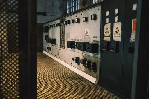
NC contacts are the default for the safety portion of an interlock because any single failure (broken wire, loose terminal, contact weld) pushes the system toward the safe state: the chain opens, the safety relay drops out, the contactor de-energises [S3]. NO contacts in the same chain can hide a broken wire, because an open circuit looks identical to a healthy open contact; the controller sees nothing wrong and the machine keeps running with the guard open [S3].
This is why IEC/EN 60947-5-1 specifies positive (mechanical) opening for NC safety contacts, and why dual-channel 2NC wiring is the pattern demanded for Performance Level d under ISO 13849-1 [S3]. In a selector-switch-plus-relay build, the practical split is: use the NC contact of the selector (or of the relay driven by the selector) to break the safety chain, and use the NO contact for status feedback to the PLC so the controller can confirm which position the operator selected. Wiring them backwards, i.e. using a NO contact in the stop circuit, is the classic textbook failure mode that safety audits flag on first pass [S3][S5].
Wiring a door-monitoring guard with a selector mode switch and safety relay
Rockwell Automation's SAFETY-AT126B application technique wires a Trojan 5 interlock switch and a Guardmaster safety relay to a PowerFlex 525 drive with safe torque-off, and the published build is rated Category 3, PLd to ISO 13849-1:2008 [S5]. In that build, when the guard gate is opened both NC channels of the interlock switch open, the safety relay reacts by de-energising its normally-open safety contacts, and the 24 VDC feed to the drive's safe-torque-off input is removed, so the drive cannot produce torque on the motor [S5]. The two channels are monitored redundantly, and EDM (external device monitoring) feedback confirms the contactors actually dropped out [S5].
If you graft a mode selector (Manual / Off / Auto) onto the same panel, the cleanest approach is to feed the safety relay's reset/input circuit through an NC block on the selector, so the safety chain breaks whenever the operator moves the knob out of the safe operating position. The selector's NO contact can then hand off to a standard industrial relay for non-safety functions like changing the HMI face or swapping a pump, without putting any safety load on the mode switch. This is also where a relay module becomes useful on a dense panel: it consolidates 4, 8, or 16 DPDT relays on a single DIN-rail socket with shared 24 VDC busing, so the cross-wired NC pattern above fits in one footprint instead of eight.
Selection criteria: coil voltage, contact rating, and positive opening
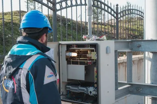
Three numbers decide which parts you actually buy. First, coil voltage has to match the control bus: 24 VDC is now the default in PLC panels, 120 VAC is still common in standalone machine builds in North America, and 230 VAC dominates retrofit work in EU panels. Mismatched coil voltage is the single most common field failure, so a 24 VDC coil on a 120 VAC rail simply will not pull in and the interlock looks like a dead switch. [S3]
Third, on the safety side, the selector switch and the relay need positive opening per IEC/EN 60947-5-1, and the contact block needs to be marked with the standard symbol (a circle with a vertical line through it on the contact) to show that the NC contact is mechanically forced open [S3]. Standard toggle and selector switches without positive opening are not acceptable in the safety chain for PLd; they are fine for the non-safety selector branch and for status feedback, but they cannot be the device that breaks the safety loop [S3][S5]. The IEC/EN 60947-5-1 minimum mechanical life for industrial control switches is typically one million operations, and quality selector switches with silver or silver-alloy contacts sit at 1-3 million mechanical cycles, which is the right order of magnitude for mode-select duty on a frequently-reconfigured machine [S3].
Who this pattern is for, and where it is the wrong tool
The selector-switch-plus-relay interlock is the right tool when you need mutual exclusion between two operating modes, when the wiring list must be readable by a maintenance electrician without PLC code, when you want a defined center-OFF rest state, and when the load is a contactor coil, solenoid, or indicator that does not need functional safety certification [S2]. It is the wrong tool when the system has more than two competing modes, when the modes must be selected by the controller rather than the operator, when the application needs PLd or higher and you have not budgeted for a protection relay or safety relay, or when the wiring environment has vibration, dust, or washdown that demands an IP67 or IP69K sealed selector rather than a 30 mm panel-mount device.
For three or more modes (Manual / Off / Auto / Bypass / Test, for example) the rotary selector is still fine, but the interlock logic should move to a safety PLC or a small angular contact bearing-grade logic relay because the cross-wired NC pattern does not scale to N states without exploding the wiring count. For purely software-managed interlocking with a single mode-select input to the PLC, a single-channel NO contact on the selector plus a software flag in the controller is acceptable if the application has no safety rating, but that pattern must be documented as non-safety, and any safety chain in the same panel must still use the redundant NC pair into a safety relay [S3][S5].
Trackable signals: parts to verify before you wire
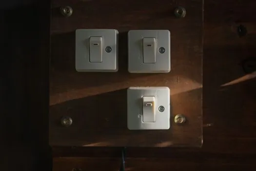
Three items to confirm against the actual build before energising: the selector switch part number must list both an NO and a mechanically-positive-opening NC contact block in the same device, the relay coil voltage must be printed on the nameplate and must match the control transformer or 24 VDC bus, and the safety relay (if used) must be configured with EDM feedback wired to the contactor auxiliaries so a welded contact is detected at the next start command [S3][S5]. A simple bench test is to apply control power with the selector in each position, measure coil voltage at each relay, and confirm that with RY1 energised the voltage at the RY2 coil terminal is below the drop-out threshold (typically under 5 V for a 24 VDC relay) so RY2 cannot pick up regardless of its selector input.
For a related decision matrix on similar discrete-control panel builds, see IEC 60477-1:2022 lab DC resistor rules for decade box selection, which covers an adjacent class of 24 VDC-coil panel wiring decisions.