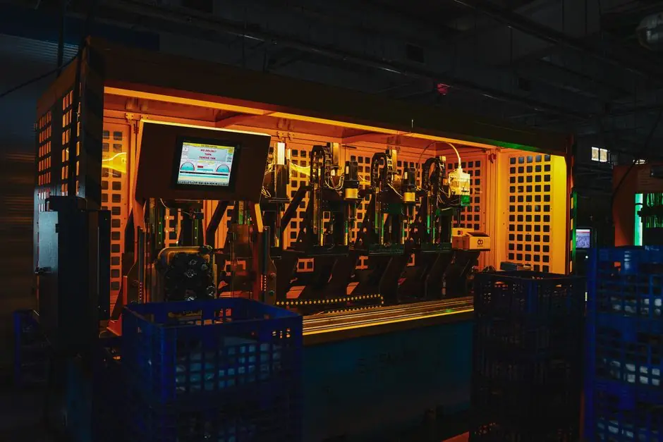
A shell core machine is a pneumatically driven, heated-platen system that cures resin-coated silica sand inside a closed core box, so installation is really a utilities project first and a machine project second [S1][S4].
Typical process outputs range from a 40 lb core at 16x16 in platen size (Redford 16, Redford 43) up to a 370 lb core at 36x44 in (Shalco U-360), and the site footprint, gas line, and electrical feed must be sized to the largest core the line will ever run, not the average [S4].
Site Prep and Foundation Tolerances
A reinforced concrete pad is the default foundation for any gas-fired shell core machine, because the heated platen assembly and sand hopper together create point loads that an industrial floor must carry without deflection [S1][S6].
Pad thickness is normally 6-8 in (150-200 mm) at 3,000-4,000 psi compressive strength, with anchor bolts set to the OEM template before the pour rather than drilled afterward, because post-installed anchors in foundry floors rarely hold torque under cyclic heating [S6]. Allow a 1.0-1.5 m service perimeter around the operator side and the sand hopper side for core box changeout and hopper refill, which on a 36x44 in platen machine means roughly 4.5 m x 4.5 m of clear floor, not the 3.0 m x 3.0 m the layout drawing often shows [S4][S6].
Ventilation is the second site constraint that gets under-scoped. Shell process cores off-gas phenolic or urea-formaldehyde resin volatiles when the platen heats above 200-260 C, so a roof-mounted exhaust canopy with a capture velocity of 0.5-1.0 m/s above the core box is the typical spec, and any installation that relies on general foundry dilution ventilation alone will fail a resin-emission walk-down [S2][S4].
Utility Hookup: Gas, Electric, Compressed Air
Shell core machines are built around three discrete utility systems, and each has a separate sizing math: heating (gas or electric), controls (electric), and process energy (compressed air plus optional hydraulics) [S1][S6].
For gas-fired units, the supply is LPG or natural gas at 7-14 in wc (1.7-3.5 kPa) for NG, with a dedicated regulator and a manual ball valve within 1 m of the machine inlet so the lockout/tagout (LOTO) point is in the operator's reach; the gas train must include a flame-fail solenoid, a pressure switch, and a pilot regulator, in that order, because reverse-order installs are the most common commissioning-day defect [S6]. For electrically heated platens, the typical three-phase feed is 380-480 V at 30-80 A depending on platen size, with a dedicated breaker and a visible disconnect within 3 m of the machine, since the cure temperature PID will not hold setpoint if the supply shares a feeder with a vibratory sand conveyor [S1][S6].
Compressed air is the most underestimated utility on a shell core install. The shooting cycle blows resin-coated sand into the core box at 4-6 bar (80-90 psi) and a 100 lb platen machine will draw 30-50 CFM of intermittent air, so the plant ring main should be sized for 1.5x the nameplate CFM and the receiver tank should be at least a 1,000 L vertical to keep the blow pressure flat during the dump valve open event [S2][S3][S6]. A 5 micron particulate filter plus a 0.1 micron coalescing filter plus a desiccant dryer is the standard FRL stack, because resin dust plus moisture in the supply line is the root cause of soft, uncured cores at the leading edge of the box [S2][S6].
Leveling, Alignment, and Core Box Mounting
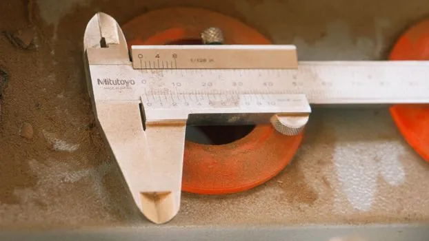
Leveling a shell core machine is a 0.05 mm/m platen-flatness task, not a "set the four corners and walk away" task, and the practical tool is a precision machinist's level on the platen face itself, not on the machine frame [S1][S6].
Sequence: shim the four primary pad feet, set platen parallelism across both diagonals, then re-shim because shimming one corner almost always moves the opposite diagonal on a 36x44 in platen. Clamping of the core box is either manual swing-bolt or hydraulic auto-clamp, and the spec to verify is the clamp force at the rated air pressure: a 16x16 in box typically needs 2,000-3,000 lbf (9-13 kN) of clamp tonnage to keep the parting line sealed at the 4-6 bar shoot pressure, otherwise the core will flash and the resin will leak out the parting line [S1][S3][S6].
Core box heating is the next alignment check. The platen is heated internally (electric) or via a gas-fired platen (LPG/NG) and the target surface temperature for phenolic-coated sand is 220-260 C with a thermocouple reading within 5 C of the setpoint across all four platen quadrants, because a 10 C gradient across the platen produces a measurable wall-thickness difference between the left and right halves of a hollow core [S1][S2][S4]. A useful acceptance test is to shoot a test core, measure the shell wall with a micrometer at four points, and confirm the wall thickness is within +/- 0.5 mm of the target before the line is signed off [S2][S4].
HMI Commissioning and Cure Recipe Tuning
Modern shell core machines ship with an HMI screen that exposes the cure temperature, shoot time, cure time, dump time, and vent time as separate recipe parameters, and the commissioning task is to build a recipe per core box, not a single recipe for the whole plant [S1][S2][S4].
Typical starting recipe for a phenolic-coated silica sand mix (roughly 95% silica, 3-4% resin, 1-2% hexa hardener) on a 16x16 in platen: platen setpoint 240 C, shoot time 2-3 s at 5 bar, cure time 25-40 s, vent/dump time 5-8 s [S2]. The cure time is the parameter to tune first, not the platen temperature, because over-cure embrittles the shell and under-cure produces a soft core that tears during ejection [S2][S4].
Acceptance criteria after recipe tune: a freely-ejected core that bends 5-10 degrees without cracking, has a uniform wall thickness within +/- 0.5 mm of the target, and weighs within +/- 3% of the calculated sand weight for the part volume. If any of those three fail, the corrective action order is: (1) check platen temperature uniformity, (2) check shoot pressure stability on the receiver tank, (3) recheck sand age and resin lot, in that order, because that sequence fixes roughly 80% of commissioning-day defects [S2][S4].
Common Installation Failure Modes and Acceptance Tests
The four recurring failure modes on a new shell core install are: (a) soft cores at one end of the box, (b) flashed cores at the parting line, (c) cracked cores on ejection, and (d) inconsistent shot weight, and each maps to a specific utility or alignment root cause [S2][S4][S6].
Soft cores at one end: root cause is platen temperature gradient above 10 C across the platen face; corrective action is re-shim the platen heater element seating and add a thermocouple at the cold quadrant; acceptance test is +/- 5 C across all four quadrants at setpoint [S1][S4]. Flashed cores at the parting line: root cause is insufficient clamp tonnage or worn clamp seals; corrective action is re-torque the clamp to rated force and replace seals; acceptance test is no visible flash at 4-6 bar shoot pressure [S3][S6].
Cracked cores on ejection: root cause is over-cure (platen too hot or cure time too long); corrective action is to drop platen setpoint 10-15 C or shorten cure time by 5 s; acceptance test is the 5-10 degree bend without cracking check [S2][S4]. Inconsistent shot weight: root cause is a leaking dump valve or an undersized air receiver that drops pressure mid-shoot; corrective action is rebuild the dump valve and add a 1,000 L receiver; acceptance test is shot weight repeatability within +/- 2% over 10 consecutive cycles [S2][S6]. If a failure persists after these steps, escalate to the OEM field service rather than continuing to tune, because the cause is almost always a worn core box, a contaminated sand lot, or a heater element that needs replacement rather than adjustment [S1][S4][S6].
Sand Tank Position and Hollow vs Solid Cores
Sand tank position is a mechanical-configuration decision the installer must lock in before the first shot, because changing it later means re-piping the blow head and re-aligning the venting [S3].
For hollow cores, the sand tank sits under the core box and the venting is on top, which lets the cure heat rise through the sand mass evenly and produces a uniform shell wall; for solid cores or complex core boxes that trap air, the sand tank is positioned on top of the core box and venting is on the bottom, which prevents air pockets that would otherwise show up as unbonded sand on the core face [S3]. The two configurations are not interchangeable on the same machine without a half-day re-plumbing, so the decision belongs on the installation layout drawing, not at the bench [S3].
When Not to Install In-House
Install in-house only when the plant has a millwright crew, an electrician, a pipefitter, and an OEM-trained HMI programmer available on the same day; otherwise schedule the OEM field service for commissioning [S1][S6].
Trackable next signal: log platen-zone temperatures, shot weight, and clamp tonnage at every shift change for the first 30 days, then weekly; any drift of more than 5 C, 3% shot weight, or 10% clamp force is the trigger for a service call before a scrap incident, not after. For a deeper look at how shell core work fits alongside cold-box and hot-box lines in a mixed core room, the core machine decision map lays out the four main process families side by side, and the shell core shooter page covers the shooting sub-assembly in more detail. The shell core machine encyclopedia entry is the parent reference for the cure-temperature and resin-system numbers cited above.
Related analysis: Vision Measuring Machine Suppliers 2026: Brand Map, Spec Ranges, and Selection Notes.