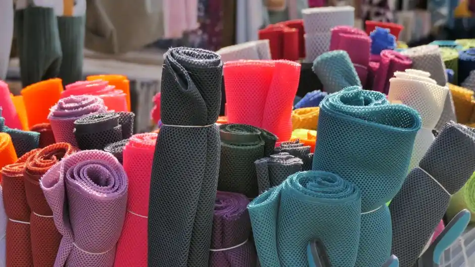
Textile mill duty cycles punish shock absorbers: looms, stenter frames, doffers, and winding carriages run at 1,800 to 2,400 cycles/hour, and absorb energy that converts almost entirely to heat, with 85% efficiency as a working baseline for typical industrial shocks [S3].
Selection for a textile line is dominated by three numbers: effective mass at the moving element, impact velocity at the moment of arrest, and cycles per hour. Anything outside that triangle is a second-order check, including ambient temperature, lubricity of the damping oil, and stroke of the absorbing element.
Impact velocity, not average velocity, drives the size
Using the system average velocity instead of the impact velocity is the single most common miscalculation in shock absorber sizing, and the gap between the two grows with deceleration profile and dwell time [S6]. On a doffer carriage that runs at 0.8 m/s average and decelerates from 1.2 m/s, the difference can be 30% to 50% of the rated energy per cycle [S6].
The kinetic energy in a linear textile axis follows the standard form E_k = (1/2) m v^2, where m is the moving mass and v is the impact velocity; an external drive that propels the mass through the stroke adds work energy E_w = F_d × S, and the two are summed to give E_t per cycle [S3]. If E_t exceeds the model rating, step up one size and recompute E_w at the new stroke, because stroke length is the lever you have for tuning absorbed energy without oversizing the body diameter.
Three shock-absorber families, three textile fitments
Industrial textile lines use three families: self-compensating (adjustable) hydraulic units for variable loads, fixed-orifice hydraulic units for constant-load axes, and pneumatic-elastic / elastomeric bumpers for low-speed, low-energy gates. Self-compensating units hold the deceleration curve roughly constant across a stated velocity range, so a 25% to 30% mass or speed swing can still be absorbed without retuning [S2].
Fixed-orifice units are cheaper and tighter in the bore, but their force profile steepens with velocity, so a small speed increase produces a disproportionately large peak force. On a constant-speed winder traverse, that is acceptable; on a loom picker stick or a jacquard shedding cam follower, the peak force spike is what kills the bearing seat. Pneumatic and elastomeric bumpers cap out at a few joules per cycle and are useful on light gates, thread cutters, and small pneumatic cylinders where a soft stop is preferred over a hard arrest.
The 30% safety factor rule at 240 cycles/hour and above
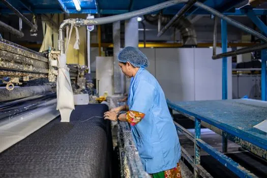
Textile machinery sits squarely in the high-cycle regime, and for cyclic rates above 240 per hour, derate the chosen unit's energy capacity by 30% as a safety margin against cumulative heat build-up and seal ageing [S4]. Heat dissipation is the silent failure mode: hydraulic shock absorbers convert kinetic energy to thermal energy through throttled oil flow, and the oil has nowhere to dump that heat except through the body wall into ambient air [S3].
For a 2,000 cycles/hour loom, hourly input E_tc = E_t × C, where C is cycles per hour, is the number to check against the absorber's hourly energy rating [S3]. If E_tc is more than roughly 60% to 70% of the hourly rating, add an external oil reservoir or a finned body, or step up one model size. The same logic applies to shock absorbers for industrial automation on stenter chain transfers, where ambient temperatures of 60 to 80 °C already sap heat sink capacity [S2].
Where textile mills break shock absorbers first
Three failure modes show up first on textile lines: oil aeration from rapid cycling, seal extrusion from peak-force spikes on mis-sized units, and rod wear from lint ingress through the wiper. On jacquard and rapier looms, the shedding cams drive reciprocating loads at 1.5 to 2.5 m/s; under-sizings here show up as oil foaming within 8 to 12 weeks, which then collapses damping force and lets the cam follower slam the seat [S3].
On stenter frames, the entry rails see wet fabric drag that varies with pick weight and finish chemistry, so the effective mass swings by 20% to 30% across a single shift. A self-compensating unit covers that swing without retuning; a fixed-orifice unit does not. For high-lint zones such as carding and drawing, a felt wiper plus an IP54 boot on the absorber rod is cheap insurance, because cotton fly packs around the rod and shortens seal life by a factor of two to three [S2].
For whom this specification works, and for whom it does not
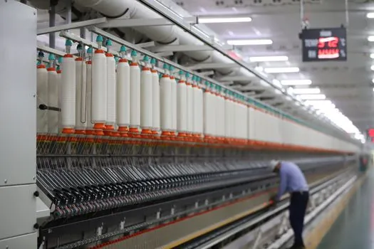
The selection logic above suits wet-processing, weaving, and knitting lines where reciprocating masses are in the 5 to 500 kg range and strokes are 25 to 150 mm. It does not suit rotor-spinning frames with very high frequency (above 20 Hz) vibration, where elastomeric isolators on the frame feet are the right answer rather than reciprocating shock absorbers. It also does not suit cleanroom man-made fibre spinning, where hydraulic oil leak risk outweighs the energy density benefit; for those cells, pneumatic-elastic buffers are the conservative choice. [S3]
For engineers who want a faster starting point, manufacturer sizing tools that accept mass, impact speed, energy absorption requirement, and cycles per hour produce a candidate set in under a minute and let you compare self-compensating versus fixed-orifice units side by side [S1]. Always cross-check the tool's output against the 30% derating rule for cycles above 240/hour, and against the impact-velocity-not-average-velocity rule, before releasing a part number to procurement [S4][S6].
Specification, standards, and what to put on the data sheet
A textile-mill shock-absorber data sheet line item should carry: energy absorption per cycle in joules or Nm, equivalent effective mass in kg, impact velocity range in m/s, stroke in mm, hourly energy capacity, ambient temperature rating, rod material and surface treatment, seal compound (NBR versus FKM for hot stenter zones), and IP rating on the wiper zone. For safety-related applications such as cutter guards and overhead doffer rails, specify a safety-class absorber with positive end-of-stroke deceleration rather than a standard industrial unit, because the failure mode of a standard unit under overload is a hard bottom-out [S2].
Two more trackable signals: first, prototypes built from precision-machined components show tighter process capability (C_pk) on damping force than cast equivalents, which is the trend in published 2025 manufacturing studies on shock-absorber repeatability [S5]; second, the move to inline condition monitoring on industrial valves and dampers is bringing integrated temperature and stroke-end sensors into mainstream catalogues, so the next data-sheet revision should ask for IO-Link or analog output on the absorber body. For broader engineering context on shock absorbers in factory automation, OEM sizing portals remain the fastest way to convert a mill's load and speed table into a short list of qualified part numbers [S1].
Detailed specification references: shock absorber, pressure transmitter, and flow meter.
See also our earlier report, Aspirating Smoke Detection for Freezer Warehouses: Spec and Pipework Read.