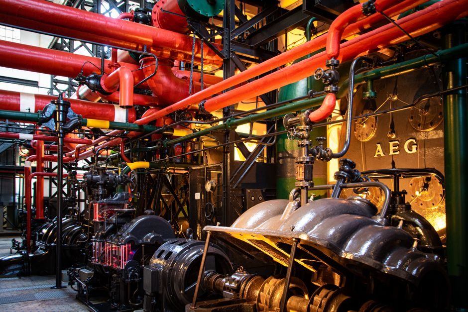
A fluid coupling transmits power through a hydraulic working fluid between a pump impeller and a turbine runner, with no mechanical contact between driving and driven shafts [S2]. Slip between input and output is intrinsic: torque-limiting fluid couplings hold rated efficiency at roughly 0.96, while speed-regulating units matched to centrifugal machinery operate between 0.85 and 0.97 [S3]. The device cannot transmit torque at all once both shafts reach the same angular velocity, a behavioural boundary that defines where the technology is, and is not, a valid engineering choice [S2].
Typical application scope covers mining conveyors, crushers, textile mills, oil and gas drives, and other material-handling equipment exposed to high engine vibration or cyclic loading [S2]. Across the Flender FLUDEX, Transfluid K/CCK, and Rexnord Falk True Torque catalogues, the published benefit list converges on smooth start, motor current reduction, and overload protection rather than on speed precision [S5][S6][S7][S9]. For a broader shaft coupling overview, the fluid coupling sits as a specialised hydrodynamic branch distinct from gear coupling and disc coupling families.
Operating Principle and the Slip Boundary
The pump wheel drives the working fluid onto the turbine runner, and the fluid momentum transfers torque across the working gap; the driving shaft and driven shaft are physically decoupled [S2]. Because the transfer depends on a velocity differential, slip is permanent: at rated load the input shaft turns faster than the output, and the lost mechanical energy appears as heat in the coupling housing [S2][S3].
The same slip that produces the soft start also imposes a hard limit: once pump and turbine reach equal angular velocity, torque transmission drops to zero and the driven machine stalls unless the motor keeps accelerating the input side above synchronous [S2]. A practical maintenance reference warns that under stalling conditions the coupling dissipates energy as heat fast enough to damage seals, gaskets, or the fusible plug, and that a stuck MTS cam lever or empty oil charge will reproduce the same stall signature even on a healthy coupling [S8].
Advantages: Soft Start, Overload Protection, and Vibration Isolation
The OEM summary lists very smooth start-ups, reduction of current absorption during the starting phase, protection of the motor and driven machine from jams and overloads, and the ability to use asynchronous squirrel-cage motors in place of soft-starter-equipped machines [S5][S6]. Because there is no mechanical contact between the pump wheel and the turbine wheel, frictional wear of the power-transmitting elements is eliminated, and power transmission is described as smooth and free from vibration noise even when the engine is a known vibration source [S2].
Vertical and horizontal mounting are both supported, and the maximum transmitted torque is set by the oil charge volume, giving the operator a single, field-adjustable parameter to match a motor to a high-inertia load [S2]. On overloading, the fusible plug melts and drains the oil charge, automatically disengaging the drive and protecting downstream equipment, a self-protective feature also highlighted in industrial maintenance literature [S2][S8]. Compared with a jaw coupling, which relies on an elastomer spider that shears under shock, the fluid coupling absorbs the same energy as hydrodynamic drag rather than as polymer fatigue.
Disadvantages: Slip, Heat, and Speed Precision
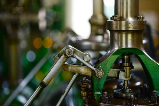
Slip is the dominant loss mechanism. Rated efficiency for a torque-limiting coupling sits around 0.96, and a speed-regulating coupling matched to a centrifugal machine drops into the 0.85–0.97 band, with the lowest figures occurring at low output speeds where the relative slip is largest [S3]. Output speed is always lower than input speed and cannot be held as accurately as in gear transmission, ruling the device out of applications that demand ratio precision [S3].
Three operational caveats follow directly. First, the fluid must be chemically compatible with seals, bladder, and housing, or transmission behaviour drifts [S2]. Second, continuous slip converts mechanical energy into heat that must be rejected through the housing, an external cooler, or a reservoir; without that thermal path the coupling will cook its own oil [S8]. Third, because the fusible plug is a one-shot thermal fuse, each overload event consumes the protective element and triggers a maintenance reset, a hidden operating cost in high-shock-duty service [S2][S8].
Selection Criteria Compared Across Coupling Options
On four decision criteria used in drivetrain specification, fluid, gear, disc, and jaw couplings separate cleanly. (1) Zero slip: gear and disc coupling options reach it, fluid and jaw coupling do not. (2) Overload protection: fluid couplings give a self-resetting torque ceiling via fill level; jaw couplings require a sacrificial spider; gear and disc couplings rely on external trips. (3) Vibration damping: fluid couplings damp through fluid shear, jaw couplings through elastomer compression, while gear and disc couplings transmit torsional vibration almost unchanged. (4) Maintenance access: fluid couplings need oil-condition checks and cooler service, gear couplings need grease relubrication, disc and jaw couplings are largely fit-and-forget. [S1]
The trade-off is consistent with manufacturer guidance: Transfluid, Flender, and Rexnord all position the fluid coupling as a soft-start and overload-shield device rather than as a precision speed-control device [S5][S6][S7][S9]. The speed-regulating variant closes part of the precision gap by adding a movable scoop tube that drains the working circuit at a controlled rate, but its efficiency band still bottoms out near 0.85, and it requires a governor circuit to hold a set point [S3].
Standards, Sourcing, and Where the Technology Fits
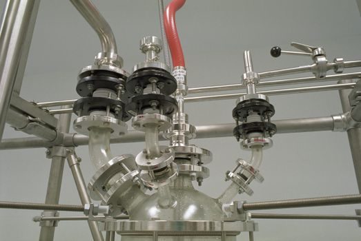
Fluid coupling design draws on the same hydrodynamic principles as a centrifugal pump, and OEM catalogues publish full performance maps indexed to motor frame size, with FLUDEX type codes FAO, FAR, FAD, FAE, FAM, FADB, FADS SB, and FADS HB covering the standard product matrix at 1500 rpm and 3000 rpm driver speeds [S7]. For process plants that need explosion-protected motors, the coupling itself adds no ignition source because there are no contacting metal surfaces, a property that pairs well with ATEX/IECEx-classified squirrel-cage motors in Zone 1 areas, although the surrounding instrumentation and seals still have to carry the certification [S5][S6].
Specifying engineers should also weigh the supply-chain footprint. Sourcing notes on adjacent industrial categories, including the phosphate rock supply chain and the manganese ore supplier map, show how the same Chinese-sourced catalogue model that delivers raw-material grade bands also delivers fluid-coupling grade bands through the same mill-equipment channels. For mining and bulk-handling duty, this overlap shortens lead time on FLUDEX-class couplings already proven in crusher and conveyor service [S2][S7].
Failure Modes and Maintenance Triggers
The published fault table for industrial fluid couplings lists excessive torque, low fill level, contact with aggressive media, and a non-responsive MTS switching element as the four root causes behind most stall or overheating events [S8]. Excessive torque is corrected by removing the downstream jam and re-checking the fill; low fill is corrected by topping up with the manufacturer-specified oil; aggressive media attack on seals is corrected by eliminating the exposure; and an MTS fault is traced to a cam lever out of position or a wiring error, both field-fixable without removing the coupling [S8].
Overheat risk is highest in two regimes: cyclic overload with short cool-down windows, and speed-regulating operation at low output where slip is largest [S3]. Operators who ignore either regime will see the fusible plug blow, lose drive, and face a coupling refill plus plug replacement before restart, an avoidable cost if temperature sensors are fitted and a cooler is sized for the worst-case slip, not the nameplate average [S2][S5][S8].
Track for the next specification cycle: tighter efficiency standards on mining drive-trains that may push specifiers from standard torque-limiting couplings toward speed-regulating units with active cooling, and continued consolidation of the fluid-coupling aftermarket around a handful of OEM brands whose spare-seal and fusible-plug inventories set the real maintenance lead time [S5][S6][S7]. Cross-check fluid-coupling selection against the peristaltic vs concrete-pump duty split and the carrying-case enclosure map when the same skid ships a hydraulic drive train alongside its control panel.