
Slewing drive selection starts with five mechanical inputs — axial load (Fa), radial load (Fr), tilting moment (M), required holding torque, and output speed — and ends with a matched bearing family plus a worm, helical, or spur gear stage. Published OEM catalogue data lists outside-diameter coverage from 300 mm to 5000 mm across the six commercial constructions used in aerial work platforms, cranes, and solar trackers [S1].
The most common drive-package build pairs a four-point-contact or crossed-roller slewing ring with an external or internal gear, then mounts a worm or planetary gearbox on the ring's driven face. Sizing is iterative: envelope OD → load capacity → gear ratio → motor torque → duty cycle. Any step forced without verifying the previous one produces a unit that either binds at first install or creeps in service.
The Five Load Inputs That Drive Every Calculation
Axial force Fa and radial force Fr are read from the lifted load, arm geometry, and any horizontal wind component on the structure; on a knuckle-boom aerial platform a 10 kN platform load can resolve to 18–25 kN equivalent Fa once the moment-arm is resolved through the slewing axis [S1].
Tilting moment M (kN·m) is usually the binding input: the product of the lifted load and its horizontal offset from the slewing axis, plus any overhanging counterweight contribution. Specs on FH-type M-series envelopes quote static tilting-moment capacity bands of roughly 5–250 kN·m across the 300–5000 mm OD range [S1].
Holding torque is the static back-driving resistance the drive must hold with no motor current — critical for inclined-axis solar trackers and personnel lifts where power loss must not back-rotate the platform. Output speed for a 1-rpm solar tracker versus a 2-rpm crane slewing axis changes the worm-ratio requirement by a factor of two with no change in load.
Bearing Family Comparison: Six Constructions, One Decision Tree
Single-row four-point-contact ball slewing rings are the default low-cost, light-tilt choice: one groove carries the combined Fa, Fr, and M; raceway hardness sits around 55 HRC after induction quench on 42CrMo or 50Mn forged rings [S1]. Typical OD envelope 300–3500 mm, dynamic load ratings in the 50–1500 kN band depending on ball diameter and raceway conformity.
Single-row crossed-roller slewing bearings replace balls with cylindrical rollers oriented 90° to each other, roughly doubling the static tilt-moment capacity per millimetre of raceway width over the equivalent four-point-contact design [S1]. They are the right pick for high-M / low-Fr applications such as robot bases and medical C-arms; the trade-off is tighter clearance control and a higher price-per-kN·m.
Double-row ball and three-row roller constructions cover the heavy end. Three-row roller designs carry two dedicated axial roller rows plus one radial row, so OD 1500–5000 mm units routinely deliver 1.5–3× the moment capacity of a four-point-contact unit at the same bolt-circle diameter [S1]. Thin-section light and flange types compress cross-section height to 25–60 mm for weight-sensitive rooftops and small trackers.
Material baseline across all six is forged 42CrMo, 50Mn, or 42CrMoV with through-hardened or induction-hardened raceways; surface hardness 55–62 HRC is the quoted band for M-class industrial series [S1].
Gear Stage and Ratio: Worm, Helical, or Spur
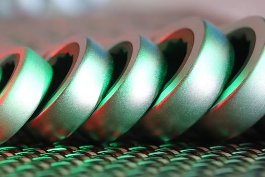
External gear (the most common modular form) bolts a worm or planetary reducer to the driven face with a pinion meshing on the ring's outer teeth. Internal-gear builds wrap the pinion inside the ring, which reduces the package OD and protects the teeth — common on enclosed solar trackers and tower cranes exposed to grit [S1].
Helical gear stages push efficiency into the 90–95% band but lose the self-locking trait, so a separate brake is mandatory for any lift application.
For more on reducer selection in adjacent motion-control stacks, see the helical gear reducer sizing walkthrough and the supplier map for 2026 sourcing.
IP, Lubrication, and Enclosure Choices for Harsh Sites
Enclosure class for a slewing drive is sized by the host environment: IP54 is the floor for indoor crane cabins, IP65 for outdoor solar, and IP66 with a sealed grease nipple cover for marine and dusty quarry duty. Gearbox oil bath versus grease fill is a duty-cycle decision: continuous slewing (tower crane) uses oil bath with a 1000–2000 hour change interval; intermittent (solar tracker, 1–2 cycles/day) uses semi-fluid grease packed for 5+ year service [S1].
Operating-temperature band on commercial M-series units is typically -30 °C to +80 °C with standard NBR seals; cold-climate builds specify low-temp grease (synthetic PAO with pour point below -40 °C) and silicone wipers on the lip seal. Hot-mill and foundry builds shift to fluororubber wipers and high-temp EP grease — the FKM selection notes cover the seal-elastomer decision in more detail.
Encyclopedia Anchors and Cross-Reference

For the foundational geometry of the raceway that the loads above act on, see the slewing bearing and slewing ring bearing references. The full packaged unit — bearing + gear + seal + motor flange — is covered under slewing drive. Where the application is a precision linear axis in the same machine (such as a telescope mount or a CNC rotary table), a linear guide or crossed roller guide typically handles the secondary axis. A high-cycle automation line driving the slewing drive through a servomotor is most often commanded by a servo drive rather than a contactor-and-VFD pair. [S1]
Selection Criteria at a Glance
On a 1-rpm solar tracker, the four-point-contact ball slewing ring with an external gear and 60:1 worm is the cost-default; the moment per OD ratio is the lowest, but the hold-back torque and price are also the lowest, so the spec is justified. On a knuckle-boom lift that needs sub-arcminute pointing and zero backlash, the helical-drive crossed-roller build is the right pick: roughly 2× the moment capacity per millimetre of width, and the helical stage gives the smooth reversals a worm drive cannot. [S2]
On tower cranes slewing at 1.5–2 rpm under continuous duty, the three-row roller ring with internal gear and oil-bath lubrication is the only honest spec — the radial-row track is what handles the off-axis wind moment the other families derate hard against. For a 200 mm envelope inside a small medical robot, the thin-section flange type collapses the section height to ~25 mm and still gives the four-point-contact geometry, which is usually enough moment capacity at that OD.
Track the supplier-side angle on adjacent gear-reducer sourcing: the helical gear reducer picks for semiconductor tools cover the precision end of the same selection logic, while variable speed drives for automotive addresses the motor-side spec bands the gearbox sees. Verified M-series envelope coverage sits at 300–5000 mm OD with three gear options (external, internal, no gear) per the published 2026 catalogue [S1].