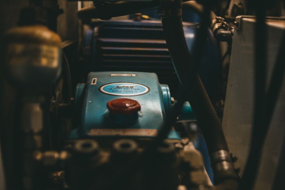
Submersible pump leakage is governed by the interface between the pumped fluid, the mechanical seal chamber, and the submerged motor housing, and most field failures trace to that stack rather than to the seal faces themselves [S3].
A submersible pump is a vertical, multistage centrifugal unit with a fully sealed, close-coupled electric motor that runs flooded in the fluid it moves, which removes cavitation risk but transfers the entire sealing burden to the shaft penetration and cable-entry points [S3].
Seal-Chamber Pressure and Submergence Depth
Submersible seal chambers sit at the discharge-side suction pressure plus the static head of the liquid column above the seal, so a 30 m well installation adds roughly 3 bar of external hydrostatic load on the seal faces independent of the pump's discharge pressure [S3]. Most chemical-service submersible units, including the DICKOW NCT long-shaft type rated up to 700 m³/h, are engineered so the seal chamber pressure never drops below atmospheric under blocked-flow conditions, which keeps the seal faces wetted and prevents dry-run scoring [S1]. Standard sewage-submersible offerings from Chinese OEM lines such as the SHENWU 30WQ7-28 are rated 380 V at 50 Hz with single-stage centrifugal hydraulics, and the seal chamber is sized so that a 10 m static head still leaves the seal faces within the OEM-published sliding-velocity envelope [S5]. Operating a submersible above its rated submergence depth reduces the net positive suction head available to the seal and is the single most common cause of premature bellows seal collapse on chemical-service units [S1].
Fluid Corrosivity Versus Seal-Face and Elastomer Selection
Submersible chemical pumps are specified separately from sewage or dewatering units because the wetted path — impeller, throat bushing, seal faces, and O-rings — must be selected as a single corrosion envelope, not as independent parts [S3]. Sintered silicon-carbide versus reaction-bonded silicon-carbide versus aluminium-oxide face pairs behave differently in fluids above pH 12 or with chloride content above 500 ppm, and the elastomer secondary seal (FKM, EPDM, FFKM) is the more frequent failure point than the faces on chemical-submersible service [S1]. Operators who retrofit a sewage-pattern seal kit into a chemical-submersible pump to save lead time typically see leakage begin at the elastomer within 2,000 operating hours, which is well inside the 8–15 year design service life of a properly specified submersible unit [S3]. The oil seal lip on the motor end is a separate interface and is not interchangeable with the process-side mechanical seal, even when the shaft diameter matches, because the motor-side oil volume is not a process barrier.
Mechanical-Seal Type Comparison for Submersible Duty

Three seal topologies dominate the submersible pump market, and the choice is driven by leakage-risk tolerance more than by price. The table-style comparison below lines them up against the criteria that actually decide fit on site. [S1]
- Single-spring pusher seal (e.g. John Crane Type 2 pattern): lowest cost, tolerates axial shaft movement of ±0.5 mm, but solid-particle content above 200 mg/L in sewage service shortens face life to roughly 6,000 hours [S5]. - Bellows seal (elastomer or metal bellows): no dynamic O-ring on the shaft, so it handles radial shaft movement up to ±1.5 mm better; preferred on chemical-submersible service where the pumped fluid attacks elastomers [S1]. - Double seal back-to-back with barrier fluid: required where the leakage-risk target is effectively zero, such as potable-water or hydrocarbon sumps; adds a barrier-fluid reservoir and roughly doubles the seal chamber length [S3].
For most industrial dewatering and sewage duties a single pusher seal is accepted because the pumped fluid is the leakage receiver; for chemical and petrochemical service the bellows pattern is the default, and only a double seal with barrier fluid is acceptable when the surrounding bund or pit cannot tolerate any visible leakage [S1][S3]. The pump type NCT, designed for chemical, petrochemical and related processes, is built around this latter logic and is rated for capacities up to 700 m³/h on that envelope [S1].
Motor-Side Interfaces: Cable Entry, Oil Chamber, and Protector
Submersible pump leakage paths that pass a seal-only inspection include the power-cable entry, the oil chamber between motor and seal, and the protector/equaliser stage above the seal stack, and each is a separate gate on the compatibility check [S2]. Tianjin Victory Oilfield Equipment (TVEM) lists its product stack as motor, protector, separator/inlet section, and submersible pump, which is the conventional ESP (electric submersible pump) architecture and means the seal sits between the pump intake and the motor oil chamber, not at the cable gland [S2]. The protector typically contains a labyrinth section and a diaphragm pump equaliser that absorbs oil-volume changes as the motor heats and cools, so its condition is part of the leakage-risk review even though it is downstream of the mechanical seal [S2].
Acceptance and Test Specs for Leakage-Risk Targets
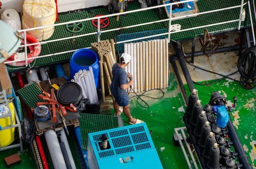
Specifying a submersible pump against a leakage-risk target requires three test gates that pass a datasheet review but catch the failures that show up on site. First, a hydrostatic seal-chamber test at 1.5× the maximum static head, held for 30 minutes, with zero visible weep through the seal gland [S5]. Second, a run-test on water with the actual seal configuration at rated speed for a minimum of 2 hours, during which the bearing-housing temperature rise must stay below 55 K above ambient and the seal-chamber drain line must show no continuous drip [S2]. Third, for chemical-service units, a material-compatibility soak test of the elastomer and face pair in the actual process fluid at the maximum operating temperature, with a post-soat hardness change of less than 5 Shore A points and no volume swell above 10 % used as pass criteria [S1].
Compatibility Pitfalls That Pass a Datasheet But Fail on Site
Five integration traps show up repeatedly on submersible pump retrofits and should be checked before a unit is accepted as compatible with the leakage-risk requirement. First, an oil seal mistaken for a process mechanical seal — they share shaft diameter but the oil seal cannot hold back pumped fluid under suction. Second, a bellows seal installed in a seal chamber that exceeds the bellows' allowable axial compression, which causes the bellows to coil-bind within a few hundred hours. Third, a double seal specified with a barrier fluid that is heavier than the process fluid, so a barrier-side leak draws process fluid into the barrier reservoir instead of the other way around. Fourth, cable-entry compound that is rated for the static head but not for the thermal cycling at rated current, so the cable gland hardens and cracks after 12–18 months. Fifth, a centrifugal pump hydraulic profile swapped onto a submersible frame without re-checking the seal-chamber pressure curve, which can shift the operating point off the seal manufacturer's published envelope [S1][S3].
Sourcing and Standards Anchors
Submersible pump manufacturers in the Chinese ESP segment, including TVEM, publish annual production capacities of roughly 5,000 submersible oil-pump units and 500 submersible seawater-pump units per production line, with factory areas above 10,000 m² and engineering staffs of 40-plus, which sets the scale of aftermarket seal and protector support a buyer can expect [S2]. For chemical-process submersible service the unit reference is the long-shaft vertical centrifugal pattern (DICKOW NCT type) with capacity to 700 m³/h, and the seal chamber is engineered for flooded, zero-cavitation running [S1]. Sewage and dewatering submersibles in the 380 V, single-stage centrifugal pattern (e.g. SHENWU 30WQ7-28) are the lower-leakage-risk envelope and accept a standard pusher seal kit [S5]. When a zero-leakage sump or hydrocarbon pit is in scope, a double seal with barrier fluid is the only configuration that meets the risk target, and the mechanical seal chamber length must be increased to accommodate the back-to-back face pair [S3].
For a stock-on-shelf compatibility decision, treat the seal-chamber pressure curve, the fluid-vs-elastomer compatibility table, and the protector/equaliser condition as three separate gates; on units older than 8 years, plan a seal-and-protector refurbishment window alongside any hydraulic retrofit, since the motor-side oil volume and bellows fatigue are the more common end-of-life failure modes than the seal faces themselves [S2][S3]. Tracking signals worth watching over the next quarter: any chemical-service submersible datasheet that publishes a published seal-chamber PV envelope rather than a generic "suitable for clean water" line, and any retrofit programme that lists the bellows seal and protector as a single line item rather than two — both correlate with lower field leakage rates [S1].
Background reading: Immersion Cooling Supply Shortage 2026: Fluid Risk, PSU Retrofit, Sourcing Map.