Clean bore, half-threaded hole pattern, and torque-wrench discipline separate a working taper bush from a walking sheave — Martin and Taper-Lock installation sheets converge on the same seven-step sequence for sizes 1008 through 120100 [S2][S3][S4].
The taper bush is a flanged, longitudinally-split steel sleeve with a shallow taper on its OD; tightening axial cap or set screws through the hub threads wedges the inner bore onto the shaft and the OD into the hub taper simultaneously, producing a friction fit on both interfaces. Standard catalog bore coverage spans 1/2 in. on the 1008 up to 6 in. on the 6050, with bushings above 1008 typically using 1/2-13NC or 5/8-11NC cap screws [S2][S6].
Bushing Families and Where Each One Fits
Three product lines dominate conveyor and power-transmission specs: BTL (Chinese-origin metric/dual, used widely on small sheaves) [S1], Martin Taper-Lock (the workhorse 1008-120100 series on ANSI B15.1-compliant drives) [S2], and the QD/HE family used where higher torque density or larger bores are required [S8]. All four share the same locking principle — a tapered split sleeve plus axial fasteners — but they are not interchangeable; hole counts, screw sizes, and recommended torque values differ family to family, so cross-brand mix-ups will under-torque or strip threads on the first start [S4][S8].
For a deeper look at how the bush sits in a larger mounted assembly, the taper bush encyclopedia page covers the geometry and torque-wedge mechanics. Taper-Lock and BTL share the 1008-3030 small-bore range and the 3535-6050 mid range, but Taper-Lock extends to 120100 for shaft diameters above 6 in. while BTL tops out at 5050 in most catalogs [S1][S4][S5].
Clean-and-Degrease: Why Lubricant on the Taper Is a Failure Mode
Taper-Lock installation sheets explicitly warn "Use NO lubricants on the bushing body or hub bore" because oil on the OD taper drops the static friction coefficient enough that the wedge slips on first impact load or thermal cycling, leaving the sheave loose on the shaft [S4][S5]. Martin's instruction sheet mirrors this: step 1 is to "clean all oil, dirt, and paint from shaft, bushing bore, outside of bushing and component bore" [S2][S3].
Symptom of a lubricated taper is rotational scoring at the hub/bore interface after 50-200 hours and a sheave that walks axially under V-belt pull. Root cause is reduced Coulomb friction at the OD taper. Corrective action: remove the bushing, degrease both contact surfaces with isopropyl alcohol or an approved cleaner, and reassemble dry. Do NOT add thread-locker as a substitute; if the joint slips dry, the bore tolerance or screw torque is wrong, not the surface chemistry. Acceptance criterion after re-install: torque-wrench reading on a re-tap cycle must match the as-installed value within one click [S3][S7].
Hole Pattern: Half-Threaded Holes, Not Threaded Holes

Every taper bush in the 1008-6050 range is drilled with a pattern where each through-hole is tapped on one side only — installation screws must engage those half-threaded holes so that tightening drives the bushing axially into the hub, not radially into the shaft [S2][S3][S7]. Inserting screws into the wrong (untapped) half gives a false torque reading because the screw bottoms in the hole before the bush is wedged; the hub will walk on first load.
Symptom: a sheave that rotates true on installation but slips within minutes of the first full-torque start. The diagnostic is to count screws against the drawing — for a 1008, exactly 2 screws are used, both in the ❍-marked half-threaded holes, not in the l-marked removal holes [S7]. Corrective action: back out screws, re-seat the bush with screws only in the install half of the pattern, then re-torque in alternation. PCI's installation sheet for QD/HE/Taper-Lock warns that factory-assembled units may have arrived below spec torque, so re-torque on receipt is mandatory [S8].
Torque Tables: 1008 to 6050 by Screw Size
Recommended wrench torque is graded by screw size, not by bushing size, because the bushing acts as a wedge and the screw only sees a fraction of the assembly clamping force. PPI's OM-023 sheet gives a clean ladder: 1/4-20NC screws on the 1008 torque to 55 lb·ft, 3/8-16NC on the 1610/1615 to 175 lb·ft, 7/16-14NC on the 2012 to 280 lb·ft, 1/2-13NC on the 2517/2525 to 430 lb·ft, and 5/8-11NC on the 3020/3030 to 800 lb·ft [S6]. BTL's chart on the 1008-3030 range matches the 55-800 lb·ft ladder within ±5%, with the 3535-5050 range stepping up to 9/16-18NC and 1,250 lb·ft for the largest units [S1][S6].
For comparison against decision criteria, the four practical gates are screw size, torque value, hole count, and whether the size requires the hammer-and-block re-tap step. A 1008 needs two 1/4-20 screws at 55 lb·ft with no re-tap; a 2517 needs two 1/2-13 screws at 430 lb·ft with no re-tap; a 3535 needs three 1/2-13 screws at 430 lb·ft plus the hammer-and-block step; a 6050 needs three 5/8-11 screws at 800 lb·ft plus re-tap and grease fill of unused holes [S1][S6][S7]. When the required torque is not in your wrench range, the bushing is the wrong size for the available tooling — escalate, do not guess.
Large-Bore Re-Tap: Why 3535 and Up Need Hammering

On sizes 3535 and larger, the bushing's mass and the hub's contact area are large enough that the first torque pass leaves a small gap at the large (rear) end; without a mechanical re-tap, the screw reaches its torque value before the wedge is fully seated, and the assembly loosens under load [S2][S3][S7]. Martin's instruction is explicit: use a block, sleeve, or drift and hammer the large end of the bushing — never the bushing directly — then re-torque to the same value; repeat until the torque-wrench reading after hammering equals the reading before hammering [S2][S3][S7].
Symptom of skipped re-tap: screws pass torque on installation, the sheave runs true for 10-30 minutes, then begins to slip with a low-frequency chatter as the wedge settles. Root cause is trapped air in the OD taper interface. Corrective action: back out screws one turn, set the re-tap block against the large end, strike the block 2-3 times with a 2-4 lb hammer, then re-torque to spec and compare against the prior reading. Acceptance criterion: post-strike torque must equal pre-strike torque within one wrench click. If the reading drops, the joint was still moving; repeat [S7]. On the 1008-3030 range the re-tap step is omitted because the bush mass is too small for the air-gap effect to dominate [S2][S4].
Removal: The Other Half of the Pattern
Each taper bush has a second set of holes offset from the install holes — these are the removal holes, marked with an "l" on the Martin and Taper-Lock drawings, and they are the ones you thread screws into when you want the bushing to walk out of the hub [S2][S3][S4]. Tighter screws do not "pull" the bush in; they push it. Removal is therefore a controlled axial push: install screws in the removal half of the pattern, tighten alternately, and the bush slides out the back of the hub without a puller [S3][S4].
Symptom of using the wrong holes for removal is a stripped screw or a cracked hub web — operators try to drive a 5/8-11NC screw against an untapped hole, the screw bottoms, the operator keeps turning, and the screw shears at the thread root. Corrective action: confirm the removal hole pattern against the catalog drawing before turning any screw, and stop the moment a screw stops getting harder — that is the geometric limit, not a stuck joint. Acceptance criterion for re-install: a removed and re-installed bush must still pass the same torque-table check on its return to service, with no more than ±10% deviation in screw torque across the pattern [S2][S7].
Grease Fill, Re-Use, and When to Replace
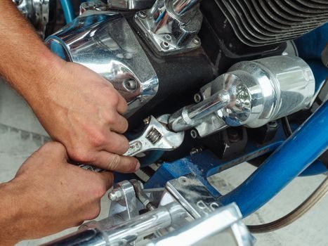
Step 7 of the Martin install — fill all unoccupied holes with grease — is corrosion prevention for the screw threads, not lubrication of the taper [S2][S3]. Skipping this step on outdoor or washdown-duty drives leads to thread galling at the next removal, which is the most common reason a 10-year-old taper bush will not come out of its hub cleanly. PCI's separate QD/HE/Taper-Lock sheet adds a useful rule: factory-installed shafts may arrive below spec torque, so re-torque cap and set screws with a calibrated wrench before first start, regardless of whether the assembly looks tight [S8].
Re-use is acceptable if the bushing shows no axial scoring on the OD taper, no brinelling at the screw-bearing flats, and the bore roundness is within 0.001 in. TIR on a V-block and dial indicator. Replace the bushing if the OD taper shows a polished wear band wider than 1/8 in., if any screw hole is elongated, or if the bore is bell-mouthed beyond the spec above — at that point the wedge geometry is gone and the joint will slip regardless of torque. Comparing the four decision gates (surface finish, screw hole roundness, bore TIR, OD taper profile) against the original catalog drawing is the field-acceptance test [S2][S5][S7].
Bore-to-Shaft Matching and Keyseat
Keyseat sizing for the 1008-2517 family is published in the Martin catalog and is not the same on the bushing as on the shaft: the 1008 lists 1/8 × 1/16 bushing keyseat against a 1/8 × 1/16 shaft keyseat for bores 1/2 to 9/16 in., and 3/16 × 3/32 on both sides for 5/8 to 7/8 in. bores; the 1210 keeps 1/4 × 1/8 on the bushing against a 1/4 × 1/8 shaft keyseat through 1-1/4 in. bore [S2]. A mismatch here — bushing keyseat deeper than shaft keyseat — is a classic cause of a key that rides up and locks the bush on the shaft before the taper has seated, giving a false-torque reading at install [S2][S5].
For comparison, the four decision criteria when matching a bore to a shaft are: bore diameter within the catalog range for that bushing number, keyseat width on bushing and shaft within ±0.005 in., shaft tolerance h6/h7 for a press-friction fit, and shaft surface roughness below 32 µin Ra. The shaft itself is not the same spec as the bushing bore — drill-rod or rough-turned bar will hold a torque-wedge joint for a few hours, then slip. In a conveyor or linear guide system, the same shaft-prep rule applies, and the failure modes (walk, slip, fret) are identical.
Safety Guarding and Standards
All rotating power-transmission products when used in a drive are potentially dangerous and must be guarded as required by applicable laws, regulations, and standards, with the Martin and Taper-Lock sheets explicitly referencing ANSI B15.1 (Safety Standard for Mechanical Power Transmission Apparatus) [S2][S3]. ANSI B15.1 governs the guarding, not the locking torque; it is the lockout/guards envelope around the bushing/sheave/shaft assembly, not the screw-tightening value. Operators must also follow OSHA 29 CFR 1910.219 (Subpart O) for rotating equipment, which references B15.1 directly in most U.S. jurisdictions.
For European CE-marked machinery, the same locking principle is used but the standards chain is EN ISO 13849 (safety-related parts of control systems) and EN 60204-1 (electrical equipment of machines), with the taper bush itself covered by the drive-component supplier's declaration of incorporation. A practical field test: with the machine locked out, try to rotate the sheave against the shaft by hand — there should be zero relative motion and no audible tick. If the sheave ticks under hand force, the wedge is not seated and the joint will fail under motor starting torque [S2][S8].
Common Failure Modes and Acceptance Test
Four failure modes cover roughly 90% of field service calls: walking (axial migration, root cause under-torque or contaminated taper), slipping (rotational slip, root cause over-lubricated taper or worn OD), fretting corrosion (root cause micromotion from under-torque or wrong keyseat), and frozen bushing (root cause galling or corrosion in the screw threads, almost always from skipped grease fill) [S2][S4][S5]. Walking and slipping are installation issues; fretting is an installation plus duty-cycle issue; freezing is a maintenance-history issue.
Acceptance test after any install or re-install: torque-wrench re-tap on the large end for 3535+ sizes, then a no-load hand check that the sheave cannot be rotated against the shaft. Run unloaded for 5 minutes and re-check torque; if any screw has dropped more than 1/4 turn, the joint is not stable. If two cycles show a drop, the bushing or hub is the wrong pair — replace, do not re-torque harder, because over-torque on a worn taper cracks the hub web. For comparison against other shaft-mounted connections like a shaft collar, the taper bush gives higher torque density at the cost of being non-reversible without tooling.
Sourcing Notes and Trackable Signals
BTL, Martin, Taper-Lock (TB Woods), and QD/HE (PCI) are stocked through industrial distributors with published torque sheets; lead time on common 1008-3030 sizes is typically 2-4 weeks ex-warehouse for OEM-pack quantities. The first signal to track is revision date on the manufacturer's installation sheet — Martin and Taper-Lock have both issued updates in the last 36 months, and an old PDF on a maintenance PC is the most common root cause of a 2026-dated failure with a 1990s procedure. The second signal is screw-grade marking on replacement cap screws: Grade 5 is the default, Grade 8 is required for 3535+ sizes in cyclic-load applications, and a 10.9 or 12.9 metric substitute will not seat the same way because the thread-pitch difference alters the wedge force [S6][S8].
For component-level specifications, see crossed roller guide.