
Bridge-site TIG work converges on a tight machine envelope: AC/DC inverter output from roughly 5 A on the low end to 230–400 A at the high end, 3-phase 380–480 V primary input (with single-phase 220–240 V fallback on small deck-panels), high-frequency (HF) non-contact arc start, and pulse-width modulation for heat input on thin-gauge stainless rebar splices [S3][S5].
Process choice on a bridge is not abstract: deck-panel aluminum (5052/5083 series), structural stainless rebar (typically 12–25 mm), handrail chrome-moly (4130), and architectural weathering-steel trim each punish the wrong waveform, and a TIG welder spec is judged against the joint, not the brochure [S1][S5].
Why bridge TIG specs diverge from a fab-shop TIG
Site duty cycle, not lab duty cycle, is the binding spec. A bridge TIG is expected to run at 60% duty cycle (some 60–80% on inverter units) at rated output, in open air, on dirty or wet rebar, often from a generator set that drifts ±10% on frequency, so a wide input tolerance window (typically 380–480 V, 50/60 Hz) and generator-tolerant filtering are non-negotiable [S3].
Generator compatibility also forces inverter topology. The PULSETIG-200 reference design is an inverter-based full-bridge micro-process control portable welder, which is the architecture most modern site TIGs share because IGBT full-bridge stages tolerate generator noise far better than legacy transformer-rectifier sets, and they shrink weight from ~80 kg (transformer) to under 25 kg for a 200 A class unit [S4].
Output range and AC balance: the real decision matrix
For a 5–230 A range on a portable inverter, you can weld 24-gauge stainless up to roughly 1/4 in. (≈6.4 mm) aluminum in one machine, which is the band most bridge handrail, light deck-panel, and sign-gusset work sits inside [S5].
For thicker bridge members, 1/8 in. to 3/16 in. aluminum welds require at least 200 A of headroom; below that ceiling you cannot push enough current into aluminum without losing the cleaning action AC balance provides [S5].
DC-only machines are disqualified for aluminum bridge work, which eliminates a large slice of low-cost inverter TIGs marketed for stainless and mild steel only [S3][S5].
HF start, pulse, and foot-pedal control: operator-side specs
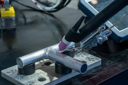
High-frequency non-contact arc start is the bridge default: it lets the operator strike without scratching the workpiece, which matters on polished stainless handrails and pre-positioned rebar where contact-start tungsten inclusions would fail inspection [S1][S3].
Pulse control (typically 0.5–500 Hz on modern inverter TIGs) lets the welder drop heat input between pulses, which is how thin-gauge bridge components (sign panels, architectural reveal trim, ornamental rail) get welded without distortion; on deck panels this same control is what makes walking-cup automated TIG feasible [S4].
A foot-pedal amptrol, or a finger-tip amptrol on the torch, is the third operator-spec, because TIG on a bridge is almost always current-pedal work, not pre-set current work, and a welding cutting tool spec without a real amptrol interface is not a real bridge TIG [S1].
Comparing the main options a site engineer picks between
The real choice on a bridge is not TIG vs not-TIG, it is between four machine classes. The table below lines them up on the criteria that actually matter at the joint. [S4]
Class A: portable AC/DC inverter, 200 A class, 5–200 A output, single-phase 220–240 V, ~13–25 kg, HF start, pulse, AC balance; good for handrail, sign structures, thin-gauge stainless trim, and short deck-panel runs on small bridges [S3].
Class B: site-grade AC/DC inverter, 300–400 A class, 3-phase 380–480 V, 25–40 kg, HF start, pulse, AC balance, foot-pedal, water-cooled torch option; this is the workhorse for box-girder stiffener splices, larger deck panels, and stainless rebar cage work [S3][S4].
Class C: engine-driven welder/generator (diesel, ~300–500 A DC, sometimes AC), 400–700 kg; used where grid power is absent, but AC aluminum duty is limited and pulse is rare, so it is a fallback, not a first pick [S3].
Class D: orbital/crawler TIG rig, 200–400 A, water-cooled, automated traverse, used for long stainless process-pipe runs and large-diameter bridge drainage; rarely rented unless the bridge carries significant utility piping.
For comparison: Class A trades capacity for portability and works on any 220 V outlet; Class B trades portability for full bridge duty cycle and 3-phase tolerance; Class C trades weld quality for off-grid reach; Class D trades capital cost for repeatability on long runs. On a typical short-span bridge (≤40 m) Class A plus one Class B is the standard pair; on long-span or utility-bearing bridges Class B plus Class D is more common.
Standards and inspection: what the spec must satisfy
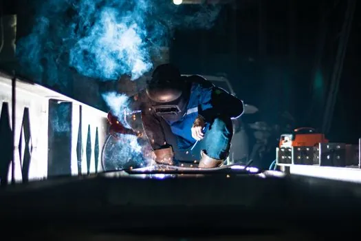
Bridge welds are inspected to AWS D1.1 (steel) and AWS D1.2 (aluminum) in the US, with equivalent EN ISO 3834 quality requirements and, for stainless rebar, often ASTM A955/A955M; the welder's job is to give the operator stable amperage, stable arc length, and clean shielding-gas coverage, which is why flow-meter calibration (typically 12–18 L/min argon at the torch for aluminum) and gas-purge line purging before strike are standard site pre-checks [S1][S3].
Stainless and chrome-moly welds on bridges are also routinely subjected to dye-penetrant or radiographic inspection, and a TIG machine that cannot hold a steady 80–120 A for a long root pass will fail inspection long before the operator does [S5].
Where TIG is the wrong tool on a bridge
Thick-plate primary structural welds (≥10 mm main girder flange) are FCAW or SAW territory, not TIG, and any procurement that pushes a Class A or B TIG into a thick-flange full-penetration splice is a procurement error, not a productivity question [S1][S6].
Field overhead-position welds on heavy sections are also not a TIG application: productivity collapses and operator fatigue spikes, so a stud welder or FCAW rig is the right construction tool for those joints [S6].
Generator pairing and power conditioning
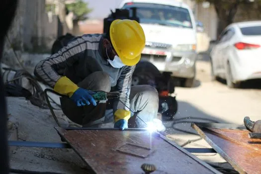
An inverter TIG rated 200–400 A draws 3-phase input around 380–480 V at roughly 20–40 A primary at full output, which is why on-site specification must include a generator sized at 1.5–2× the welder's nameplate kVA, with voltage regulation within ±10% and frequency within ±5%, or the HF start and pulse circuits will misfire [S3].
For deck-panel aluminum runs, the same pairing logic applies to water-cooled torches: a 400 A class TIG running above ~150 A continuously needs a cooler unit plumbed to the torch, otherwise the torch head overheats and the operator stops well before the duty cycle rating is reached [S4].
Related equipment decisions on the same bridge site
A bridge welder is rarely the only procurement problem on a site. For deck preparation, abrasive selection and span-by-span throughput sit on a different spec map, covered in a sister piece on sander selection for bridge construction. For lifting rebar cages and plate into position beside the welding station, an overhead bridge crane capacity check is the next procurement gate. For concrete deck groove cutting after the welds are in, blade count, power, and depth maps are scoped separately in the concrete groove cutter reference. None of these decisions overlaps with TIG output amperage, but they all share the same input-power, generator-sizing, and site-logistics envelope. [S3]
Closing node: the next trackable signals for a bridge TIG spec are (a) AWS D1.1/D1.2 amendment ballots that tighten aluminum AC-balance and pulse-tolerance language, and (b) inverter IGBT module price curves, which set the floor on Class A 200 A unit pricing through 2026. For an immediately adjacent procurement on the same site, a stud welder selection for steel construction map covers the stud-arc process used on bridge shear connectors, which usually runs in parallel with the TIG station rather than replacing it.