Smart positioners like the Metso ND9102HN7TR and MORC MSP-25 use HART 7 over a 4-20 mA loop and accept supply pressure from 1.4 to 7.0 kgf/cm² (0.14–0.7 MPa), making pre-commissioning verification the single highest-leverage step on site [S4][S5].
For a control loop to actually deliver ±0.5% F.S. linearity and ≤0.3% F.S. hysteresis as the manufacturer claims, the mechanical feedback geometry has to be within a degree or two of ideal, not the electronics [S2]. This guide walks through the procedure a process engineer or commissioning technician would actually follow on a linear pneumatic actuator in a chemical or oil & gas service.
Pre-Installation Verification: Match Nameplate to Service
Confirm the model, Ex rating, and port size against the purchase order before any wrench turns; mismatched certification is the most common field failure that gets discovered only at audit time, not at startup [S2]. For hazardous-area service, ATEX/IECEx-certified models rated for Zone 1/2 gas or Zone 21/22 dust must be specified at the PO stage, not retrofitted [S6].
For a 12-inch butterfly valve in a water supply network, a positioner with adequate Cv / air output is mandatory to overcome actuator inertia, since larger valves with higher thrust need positioners sized for the actuator volume rather than the signal type alone [S10]. Check the actuator-shaft height first: pneumatic actuators ship in 20 mm, 30 mm, and 50 mm stand-off variants, and the bracket must be ordered to match before mounting hardware is opened [S3].
Mechanical Mounting: Bracket, Lever Geometry, 50% Horizontal Rule
Standard M5×20 or M8×1.25P bolts fix the positioner to its mounting plate, after which the bracket is bolted to the actuator with a spring washer to defeat vibration loosening; the M10×15 screws then tie the plate back to the actuator yoke [S1]. On the MSP-25, the connecting-rod diameter must stay under 6.3 mm because the feedback-lever groove is 6.5 mm, otherwise the rod will bind before the lever reaches horizontal [S4].
Stroke the actuator to 50% with the air filter regulator and adjust the positioner up or down until the feedback lever is exactly horizontal (perpendicular to the valve stem); only then is the bracket hardware torqued to its final value [S4]. On the ND9102HN7TR the positioner-to-bracket screws are torqued to 4–6 N·m evenly, and free full-range movement is verified by hand before any air is applied [S5]. For linear service the ND9102 shaft coupling must be aligned with zero backlash, and the position indicator (109) is secured to the shaft with an M8 screw (110) [S5]. Refer to the valve positioner reference for the full nomenclature of pneumatic, electrical, and intelligent types covered in this install class.
Pneumatic Hookup: Port S, C1, C2, Supply Window

Supply air enters port S at 1.4–8 bar (20–115 psi) on the ND9102HN7TR, while C1 drives the actuator open and C2 drives it closed; unused ports must be sealed with metal plugs (54) and thread sealant to keep the IP66 rating intact [S5]. All positioners in this class require clean, dry, oil-free instrument air to ISO 8573-1 quality, and a soapy-water leak test is the cheapest, fastest QA step once the loop is pressurized [S5].
The standard air-consumption envelope is informative for instrument-air sizing: analog YT-1000 units draw ≤3 L/min, the compact YT-1200 ≤2 L/min, the smart YT-3300 drops to ≤0.5 L/min, and the MSP-25 reports stable-state air consumption below 0.0006 Nm³/h (essentially zero piezo bleed) with a flow capacity of 130 L/min at 6.0 bar when fully open [S2][S4]. Output pressure on the YT-1000/1200/3300/2500 family tops out at 0–10 kgf/cm², comfortably inside the 1.4–7.0 kgf/cm² supply window, leaving no reason to push the regulator to its mechanical limit [S2].
Electrical Wiring: HART 7, Loop-Powered, Shielded
The ND9102HN7TR is loop-powered from 9–32 VDC, takes 4–20 mA plus HART 7, and is reverse-polarity protected; IN+ goes to the positive signal conductor and IN- to the negative, with the shield grounded at the control system on a single point to avoid ground loops [S5]. Conduit entries on the MSP-25 come in G1/2, NPT1/2, and M20×1.5 options, and the cable gland must be torqued to keep the IP66/NEMA 4X enclosure rating after the cover is closed [S4].
The smart valve positioner reference describes the auto-calibrate / valve-signature / friction-calculation diagnostics that become available once HART 7 is locked in. Typical HART-7 smart positioners achieve ±0.5% F.S. linearity and ±0.3% F.S. hysteresis, beating the ±1.0% / ±0.5% of analog units, which is the engineering case for the upgrade on critical loops [S2].
Calibration: Zero, Span, 12 mA Mid-Point
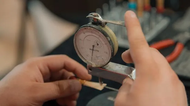
Tools required are a 4-20 mA signal generator, a digital multimeter, and hex wrenches; the procedure below is the mechanical default used when the smart auto-calibrate is bypassed or unavailable [S2]. With 4 mA applied, adjust the Zero screw until the valve just begins to move, then back it off slightly to the mechanical stop so seating force is consistent.
Apply 20 mA and trim the Span screw so the valve reaches exactly 100% stroke; the feedback lever arm should sit at 90° to the actuator shaft at 50% stroke (12 mA) for best linearity [S2]. On the ND9102HN7TR, the LUI runs a guided auto-calibrate that selects linear or rotary, sets single- or double-acting mode, runs a full stroke to auto-detect endpoints, then offers a 1-point fine-tune, with acceptance criteria of 4 mA → 0% closed, 20 mA → 100% open, smooth and stable response with no overshoot [S5]. For the MSP-25 the one-key auto-zero function plus the position-preserving-on-power-cut / air-cut / signal-cut behavior is the on-bench acceptance gate before the device is lifted onto the actuator [S4]. See the ball valve reference for how stem-friction and packing-drag values feed back into the positioner's error budget during this step.
Hazardous-Area Certification and Environmental Limits
Explosion-proof positioners in the YT-2500 / MSP-25 class carry Ex d IIC T6 (flameproof) or Ex ia IIC T6 (intrinsically safe) markings, which are the certification codes you must verify on the nameplate against the area classification drawing before energizing the loop [S2][S4]. The MSP-25 enclosure is rated Ex db IIC T6 Gb and Ex tb IIIC T85°C Db, with an aluminum or SS316L housing option for corrosive offshore or chemical service [S4].
Ambient-temperature windows differ by series: −30 to +85°C for the YT-1000, −20 to +80°C for the YT-1200, −30 to +80°C for the YT-3300, and −40 to +85°C for the YT-2500 and the ND9102HN7TR, so the cold Canadian winter or a Middle Eastern desert skid should drive the specifier toward the wider-range unit from day one [S2][S5]. For sour-gas / high-H₂S service the YT-2500 is the YTC-recommended variant, while high-vibration compressor skids favor the analog YT-1000 with a heavy bracket, since smart electronics tend to be more sensitive to sustained vibration than the analog equivalent [S2]. The balancing valve and linear guide references cover adjacent flow and motion-control hardware that typically share the same hazardous-area cabinet.
Acceptance Test and Common Failure Modes
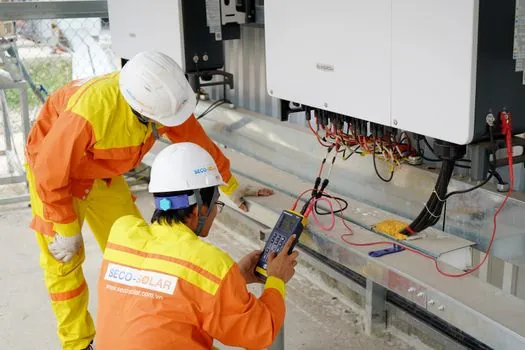
Post-install acceptance is a full 4 mA → 20 mA → 4 mA ramp with linearity and hysteresis recorded against the ±0.5% / ±0.3% F.S. spec; any non-monotonic step or a mid-point deviation above 1% is grounds to re-zero and re-span, not to ship the loop to operations [S2][S5]. If linearity is still off after two passes, the root cause is almost always mechanical: a feedback lever that is not horizontal at 50% stroke, a connecting rod binding in the lever groove, or a coupling with backlash, not an electronics fault [S4].
Do not attempt field repair of the piezoelectric valve module (P13, HOERBIGER) inside the MSP-25; the OEM recommends module-level replacement because re-seating the piezo stack without a clean-room bench typically degrades the ≤0.5% F.S. repeatability specification [S4]. The crossed-roller guide reference is a useful adjacent read for engineers sizing the mechanical rigidity of the actuator yoke that holds the positioner assembly in high-vibration service. For a wider lens on how these control-valve assemblies fit into a plant's spec gate, see the related analysis on casting mold selection for pump and valve production.