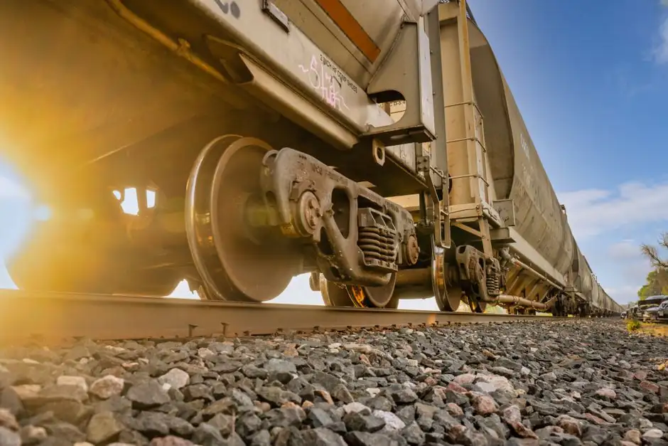
A motor-pump train on a horizontal baseplate carries 2 to 4 bearing housings (motor DE, motor NDE, pump DE, pump NDE), and each measurement point is commonly served by one accelerometer, giving a minimum of 2 and a maximum of 4 sensors for radial coverage, expandable to 6 when a third axial channel is added at one or both ends [S2][S3].
For a typical centrifugal pump set driven by an induction motor through a coupling, the textbook minimum is one accelerometer on the drive-end bearing housing of the motor and one on the drive-end bearing housing of the pump, because these two locations couple the most mechanical energy out of the shaft and into the casing [S2][S3].
Starting Point: Two Sensors, One Per Drive-End Bearing
The minimum is two accelerometers per asset: one on the drive-end bearing housing of the motor, one on the drive-end bearing housing of the pump, mounted radially (typically horizontal, 90° from the shaft centerline) for the strongest signal in the 1X running-speed band [S3].
Drive-end bearings carry the coupling reaction and the highest cyclic load, which is why even a budget installation points the first two sensors there; outboard or non-drive-end bearings are added when the program graduates from "catch the obvious" to "trend every bearing" [S2]. Frequency-domain failure modes such as inner-race spalling on the pump bearing or outer-race wear on the motor bearing sit inside the 500-2000 Hz band that piezoelectric accelerometers resolve cleanly [S4].
What Drives the Count Up: Bearing Number, Axis Count, Criticality
Machine anatomy sets the count per machine: bearing locations multiplied by the measurement axes you need, so a four-bearing train with radial and axial coverage on each end reaches 8 single-axis units or 4 triaxial units [S1].
For horizontal pump sets, the standard mounting points are motor inboard and outboard bearings, pump inboard and outboard bearings, plus casing or bearing housings near the highest vibration response; vertical turbine pumps shift that to the motor and upper bearing housings, sometimes the support pedestal where submerged-stage vibration re-emerges [S2]. Common add-on points include the discharge piping for hydraulic resonance and the baseplate for soft-foot diagnostics, each adding 1 more sensor.
Industry guidance places permanent continuous monitoring on the 15% to 20% of equipment that actually carries production, with the rest covered by walk-around or wireless interval sampling, which is why the per-machine count must be matched to an asset criticality ranking rather than a one-size rule [S1].
Triaxial and Wireless Hardware Can Shrink the Box Count
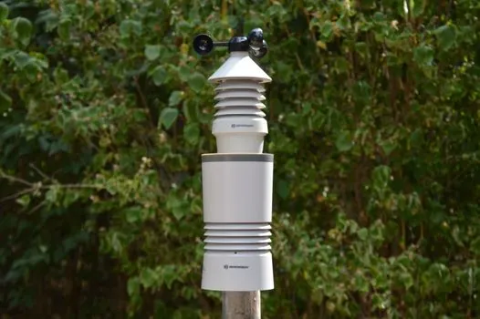
Triaxial units and wireless installs can shrink your hardware count and expand your coverage at the same time, because a single MEMS triaxial accelerometer replaces three single-axis radial-plus-axial sensors at one bearing, and wireless nodes eliminate the cable tray and conduit that often limit retrofit density [S1][S8].
For high-frequency work above 1000 Hz, where bearing and gearmesh faults live, piezoelectric accelerometers remain the better choice over most MEMS units, so the technology pick is frequency-band dependent, not brand-loyal [S4]. Wired sensors stream continuously and feed a DCS, PLC, or SCADA layer for trending; wireless sensors sample at intervals (often once per minute to once per hour depending on the criticality tier) and trade resolution for install flexibility on tanks, remote wells, and wastewater lift stations [S6][S8].
Failure Modes the Count Must Catch
Bearing defects account for over 51% of all rotating equipment failures globally, and a continuous monitoring program provides a 2-8 week advance warning window before catastrophic collapse, versus a 672-hour blind spot in a typical 28-day walk-around cycle [S3].
For pump-specific faults, a properly placed sensor array catches imbalance, misalignment, looseness, cavitation, coupling wear, and seal-related shaft movement; placement matters as much as count, because a sensor mounted on a loose baseplate or a soft foot reads structure noise, not machine health [S2][S5]. The cost asymmetry is sharp: emergency bearing replacement runs 4.8x the cost of a planned, condition-triggered intervention, which is the economic case for the extra 2 to 4 sensors per train on critical service [S3].
Where Two Sensors Are NOT Enough
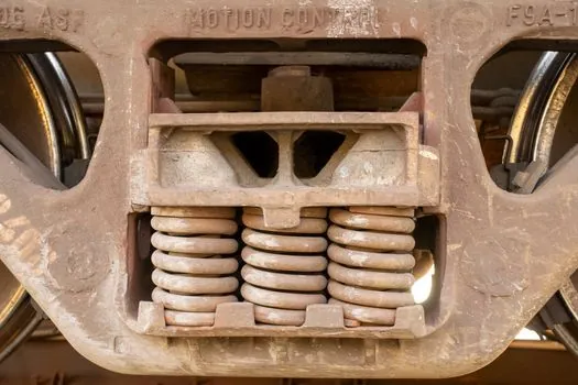
Two-sensor coverage is not enough when the pump handles hot hydrocarbons, multi-stage boiler feed, or any service where a coupling failure triggers a fire or environmental release; these trains warrant 4 to 6 sensors with both radial and axial channels, plus a casing-mounted pickup for cavitation trending [S2].
Two-sensor coverage is also short for variable frequency drive (VFD) driven pumps, where switching-frequency harmonics and bearing-shaft currents add fault modes that single-axis radial sensors miss; an axial channel at the motor NDE bearing is the cheapest upgrade to surface these [S1][S7]. Wastewater wet-well pumps, which sit on long shafts with submerged bearings, similarly need extra nodes on the support pedestal because the inboard bearing is unreachable underwater [S8].
Selection Criteria: Matching Sensor Count to Pump Service
Three decision tiers cover most plant portfolios: (1) non-critical utility pumps, 1 handheld or 1 wireless interval sensor per train, with readings taken on a 30-day route; (2) production-critical centrifugal pumps on a VFD or in API 610 service, 2 fixed accelerometers minimum, expanding to 4 with triaxial at both drive-end bearings; (3) safety- or environmental-critical pumps (hot oil, chlorinated service, main cooling), 4 to 6 fixed sensors with continuous online trending into the plant vibration condition monitoring platform. [S1]
Compare the three sensor technology options on four criteria: piezoelectric accelerometers win on frequency bandwidth (DC to >10 kHz) and signal-to-noise for bearing and gear fault detection; MEMS accelerometers win on size, cost, and triaxial integration for low-frequency (below 1 kHz) balance and misalignment work on general-purpose pumps; velocity sensors (typically 4-20 mA loop-powered, output in mm/s RMS) win on plant-signal compatibility and direct DCS/SCADA wiring without an intermediate transmitter [S4][S6][S8]. Across these three options, the practical comparison comes down to cost, frequency range, and integration: piezoelectric for high-frequency fault detection, MEMS for dense triaxial coverage, and loop-powered velocity for direct DCS hookup. For an overview of the vibration sensor family and how the different output types map to a vibration analyzer or vibration meter front end, the encyclopedia entries are a good cross-check before finalising a bill of materials.
Procurement and Sourcing Notes

Specify the sensor by full measurement chain, not by sensor alone: accelerometer with integral cable, mounting stud or magnet pad, intrinsic-safe certification (ATEX/IECEx) for Zone 1 pump skids, and an output that matches the existing monitor (4-20 mA velocity, IEPE, or wireless protocol such as WirelessHART or LoRaWAN for remote lift stations) [S2][S8].
For AC motor and drive motor trains, confirm the sensor bandwidth covers at least 5x the running speed (1X) and at least 1x the VFD switching frequency, because VFD-driven pumps excite bearing-resonance bands that a 1 kHz-limited MEMS unit will quietly miss. Order 10% to 20% spare sensors and cables with the initial BOM, because field failures of cable shielding, not the sensor element, are the dominant replacement driver in the first 24 months.
Track two signals to validate the chosen count: (1) the ratio of unplanned bearing failures in the monitored fleet versus a control group, and (2) the mean time between first threshold breach and corrective work order; if the second number stays under 72 hours, the sensor count is sufficient, and if the first number does not drop within two maintenance cycles, the program needs more nodes or better placement, not a different vendor.
For related coverage, see VDI 2198 Ast formula for reach truck aisle width: how to read the spec sheet.