Selecting a vibratory feeder comes down to four engineering gates: drive principle (electromagnetic vs unbalanced-motor resonance), trough geometry, bulk-density window, and feed rate — and a 2011 resonance-parameter study shows how granulated solids change the equation of motion versus the classical point-mass model [S1].
This matters for any line that meters molded plastic parts, electrical components, glass vials, stamped/machined hardware, or coarse mineral/chemical bulk into a downstream conveyor, weigher, or press; the wrong match shows up as rate drift, noise, or premature spring failure within months rather than years.
Electromagnetic vs Motor-Driven Resonance Drives
Electromagnetic vibratory feeders operate at 3000/3600 vpm (50/60 Hz twin-amplitude) from an AC coil pulling an armature, and are the workhorse for parts feeding in light assembly — molded plastics, connectors, glass vials, machined hardware — because the feed rate is steplessly adjustable via a thyristor-controlled amplitude setting — a closed-loop approach analogous to the control logic of a servo motor, with vibration amplitude standing in for shaft position [S2]. Motor-driven resonance feeders, by contrast, run an unbalanced motor on springs tuned near the system's natural frequency and are built for bulk tonnage: a 0.3 kW hopper with 150-180 L volume and 3-5 m³/h throughput, or the larger electromagnetic frame machine quoted at 150-300 t/h with 20-25 kW motor power in OEM datasheets [S3].
The resonance approach studied by Gerts & Gerts uses the small-parameter averaging method on an electro-dynamic microexciter to derive machine parameters from the unit surface flow cross-section, with theoretical results within the first-approximation error band of experimental data [S1]. For granulated solids, the authors note that the equation of motion varies not just in degrees of freedom but in mode conditions, so the spring/mass selection cannot be copy-pasted from a parts-feeder datasheet.
Trough Geometry, Stroke and Inclination
Linear-stroke (open-type) troughs with 0° installation slope dominate parts feeding and sanitary food/chemical transfer — the 880×880×1154 mm stainless vibratory hopper with 0.3 kW power, 220 V single phase, and 90 kg mass exemplifies the open-frame geometry sized for a weigher or short conveyor downstream, with a flow meter on the conveyor (or a load cell under the hopper) acting as the rate-loop feedback [S3]. For heavier aggregate, chute size grows: 500 mm max feeding size and 880×880 mm chute area appear on a typical mid-range linear unit, with the trough material (304 stainless for sanitary duty, mild steel with rubber liner for abrasive ore) being a separate gate from drive selection [S3].
Stroke length — set by spring stiffness, eccentric mass, and operating frequency — is what actually controls the throw per cycle. Gerts & Gerts relate the cross-section of the flow and the material consumption per unit surface directly to the machine parameters, so a "bigger motor" is not the answer to a higher feed rate; the spring/mass product has to be re-tuned to keep the system near resonance as the throughput target rises [S1].
Bulk Material Properties and Capacity Window
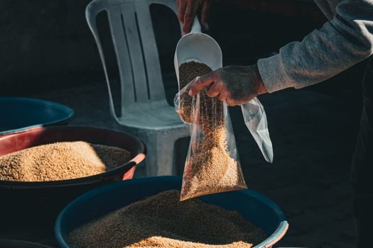
Particle shape, bulk density, moisture, and abrasiveness set the lower bound on trough liner hardness and the upper bound on vibration amplitude. The granulated-solids case in the resonance study is fundamentally different from the point-mass case because the structure of the equation changes with the number of degrees of freedom and with mode conditions — meaning the same physical feeder fed with two different powders can show two different effective spring constants [S1].
Parts feeding against this is the easier half of the catalog: bowl feeders handle molded plastic, electrical components, glass vials, and stamped or machined parts, with the bowl geometry itself acting as the orienting/selecting device, so the drive is sized for part mass (typically grams to a few hundred grams) rather than for tonnage [S2]. For mineral/chemical applications, the 150-300 t/h band at 20-25 kW is the published range, and below that the 3-5 m³/h at 0.3 kW stainless hopper covers pharma/food weigh-feeding [S3].
Selection Criteria Side-by-Side
Comparing the main options against the four gates that drive a buy decision: electromagnetic parts feeders win on stepless rate control, low noise, and sanitary stainless construction but cap out at light part weights; motor-driven resonance feeders win on tonnage (up to 300 t/h) and overload tolerance but require spring tuning and produce more acoustic and structural vibration [S2][S3].
For a 1-piece minimum order, a 304 stainless open-type linear hopper ships at US$700-900 FOB with 880×880 mm chute, 0.3 kW, 220 V single phase, 90 kg, and a 1-year warranty; the same supplier's 150-300 t/h electromagnetic frame feeder at 20-25 kW sits in a different cost class and is normally sourced against a confirmed motor-power and capacity datasheet, not the light-feeder catalog [S3]. Lead time, OEM/ODM availability, and management-system certification (ISO 9001:2015 on the sanitary line) are the last three filter gates before RFQ [S3].
Operating Limits, Failure Modes and Sourcing Signals
The most common failure modes on the wrong-sized vibratory feeder are spring breakage from running off-resonance, trough cracking at the weld seam from excessive stroke, and liner delamination on abrasive ore — each one traces back to the spring/mass/frequency combination, not to the motor nameplate. The Gerts & Gerts analysis explicitly tracks the maximal-possible error of the first approximation against experimental data, and the disagreement stays within the small-parameter error bound, so a calculated spring set is reliable only if the small-parameter assumption holds (i.e. the system is genuinely near resonance and the granular flow is steady) [S1].
Sourcing-side, FOB prices on a single-piece order range from US$180-900 across electromagnetic and pneumatic-press feeders of comparable footprint, with payment terms spanning LC, T/T, D/P, PayPal, and Western Union; average lead time is the variable that usually decides between an Own-Brand/ODM/OEM supplier and a generic Trading-listed vendor, and it should be pulled from the supplier's record rather than estimated [S3]. For related drive-side selection logic on heavy industrial equipment, the industrial magnet selection guide covers a comparable drive-and-load matching problem, and the concrete vibrator selection article walks through the same frequency/head/power trade-off from a different angle. For automation upstream of the feeder, the PLC encyclopedia entry covers the controller side of the rate-loop.
Standards, Compliance and What to Verify
No single ISO or IEC standard governs vibratory feeder selection end-to-end, but two anchors are worth pinning: the supplier's quality system (ISO 9001:2015 is the published baseline on multiple OEM datasheets in this category) and the CE/EMC conformity for the drive electronics on any 220 V single-phase or three-phase unit shipped into the EU [S3]. The resonance-parameter theory itself is from a peer-reviewed J. Mach. Manuf. Reliab. paper (2011), so the math behind spring/mass selection is auditable against the averaging method, not folklore [S1].
Trackable next signals: (1) the supplier's published average lead time in days on a comparable tonnage unit, and (2) the OEM/ODM/OEM status of the vendor — Own-Brand and ODM lines on the 150-300 t/h machine indicate real factory control, while a Trading-only vendor typically extends lead time by 2-4 weeks [S3].