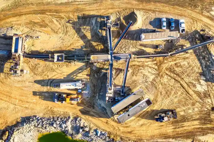
A vibratory feeder is a controlled-vibration conveyor that meters bulk solids or discrete parts into a process line, with published capacity envelopes from ounces per hour on small electromagnetic bowl feeders to several tons per hour on heavy-duty trough units [S1][S5].
The three drive families in production use are electromagnetic, natural-frequency, and out-of-balance (mechanical) units, each with distinct frequency, amplitude, and tuning behaviour; the electromagnetic variant is the most common for metering because its stroke is set by coil current rather than mechanical eccentricity [S2][S5].
Drive Types and How They Set Frequency and Stroke
Electromagnetic vibratory feeders are built from five repeatable parts: a base, an energised coil, flat leaf springs, a permanent magnet, and a tray, with the magnet fixed to the tray and the coil fixed to the base [S2]. The coil pulls the magnet toward it on one half-cycle and releases it on the other, so the flat springs store and return the energy, and the drive frequency is governed by the inverter that supplies the coil rather than by the spring mass [S2]. This is why current-controlled electromagnetic drives give a linear relationship between input current and feed rate, a property used in gravimetric feeding and remote computer control of solids metering [S5].
Natural-frequency feeders tune the tray-spring-mass system to a resonant mode, typically well below line frequency, and operate near that resonance to reduce input power; out-of-balance feeders use rotating eccentric weights and trade finer amplitude control for rugged, high-tonnage bulk service [S2][S3]. Eriez catalogues this split as Light and Medium Duty electromagnetic feeders for fine granules through micron-size material, and Heavy Duty feeders with mechanical drives for large-volume bulk screening and feed [S3].
Capacity, Trough Geometry, and Material Travel Speed
Throughput on vibratory feeders spans ounces to tons per hour, and the governing variables are trough slope angle, vibration frequency, and amplitude; travel speed on a single linear trough can be tuned from a few feet per minute to roughly 100 ft/min (about 30 m/min) by adjusting those three parameters [S1][S5]. For electromagnetic drives the leaf-spring stiffness and the tray weight together set the natural frequency, so a stiffer pack (more leaves, wider, or thicker stock) raises frequency while longer springs lower it, and matching inverter frequency to that natural frequency cuts tray stress and smooths the product jump [S2].
For vibratory bowl feeders used in parts feeding, bowl diameter is sized to roughly ten times the longest part dimension; undersizing overloads the drive unit, oversizing causes the parts to bounce without orienting [S4]. Standard bowl drive units operate between 60 and 120 Hz of vibration, which is the range most electromagnetic bowl drives are wound for, and the level-control switch on the hopper above the bowl gates refilling so the bowl neither starves nor floods [S4].
Selection Criteria: Drive, Capacity, Environment, and Integration
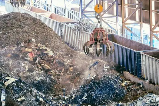
Specifying a vibratory feeder starts with four decisions, in this order: drive type, capacity envelope, environment/duty class, and downstream integration. Electromagnetic drives are the default when feed rate must track a 4-20 mA or voltage setpoint, because coil current is the control input [S5]. Heavy-duty mechanical drives are specified for tonnage-class mining, aggregate, and ore-bin service where the trough also doubles as a screen, and where totally enclosed or explosion-proof enclosures are required to meet hazardous-area codes [S3][S5].
Comparison of the three main drive types against four selection criteria:
Electromagnetic vs natural-frequency vs out-of-balance, on the criteria that drive a real purchase decision:
Frequency control: electromagnetic, variable by inverter; natural-frequency, fixed near resonance; out-of-balance, fixed by motor RPM and eccentric mass. Capacity envelope: electromagnetic, ounces to a few tph for metering; natural-frequency, mid-range bulk; out-of-balance, high tonnage bulk and screening. Amplitude tuning: electromagnetic, continuous via current; natural-frequency, limited near resonance; out-of-balance, mechanical only. Hazardous-area service: electromagnetic, available in dust-tight and explosion-proof enclosures; out-of-balance, also available in explosion-proof and water/air-pressure variants for special fire or explosion risk [S2][S3][S5].
For integration into automated lines, vibratory bowl feeders are paired with PLC controllers, level switches, pick-and-place robots, and vision systems, and the level switch on the hopper is the signal that arms the refill cycle so the bowl neither starves nor floods the downstream machine [S4].
Use Cases and Where Each Type Fits
Electromagnetic bowl feeders dominate discrete-part orientation in pharmaceutical, medical, electrical-component, automotive, aerospace, and consumer-product assembly, where the goal is to deliver one correctly oriented part per machine cycle [S4]. Linear electromagnetic feeders feed the orientated parts from the bowl exit into the next station, with the track angle and amplitude tuned to a single-file release rate matched to the host machine cycle [S4].
Heavy-duty and out-of-balance feeders dominate bulk-solid applications: ore bins, crusher feed ahead of ball mills, reagent feeders, and aggregate screening, where the same unit both meters and screens material down to a controlled top size [S3][S5]. Syntron-type electromagnetic vibrators are also mounted externally on bins and hoppers to break arches and ratholes in wet ore or sticky reagents, with the controller's dial rheostat setting the power level for the specific material behaviour [S5].
Limits, Failure Modes, and Sourcing Standards
Common failure modes are mismatched drive frequency versus tray natural frequency (excess tray stress, secondary motion, product bouncing) and undersized springs for the loaded tray mass, both of which shorten spring life and break energy transfer to the product [S2]. A non-stiff tray causes different sections to oscillate at different speeds, producing secondary motion that disrupts feed, and a too-shallow or too-steep trough slope either stalls the product or overspeeds it past the downstream station [S1][S2]. Bowl feeders fail outright when diameter is wrong: too large and the parts will not climb the spiral track, too small and the drive unit is overloaded and the bowl stalls [S4].
Sourcing and standards: hazardous-area electromagnetic and out-of-balance feeders are commonly quoted with totally enclosed, explosion-proof, or water/dust-proof enclosures, and the supplier will match certification to the zone classification of the host process [S3][S5]. The IQS Directory editorial overview of August 28, 2026 is the most current public reference consolidating types, working principles, and feeder-trough design variables into one sourcing document [S1]. For integration into a wider line, suppliers will normally quote bowl diameter, drive frequency (60-120 Hz), and the matching flow meter or pressure transmitter setpoint the feeder is meant to track, because the electromagnetic coil current is the native 4-20 mA interface into a gravimetric control loop [S4][S5].
Two trackable signals for a new spec: ask the vendor for the natural frequency of the loaded tray-spring assembly and the inverter-frequency window around it, then confirm enclosure certification (dust-tight, explosion-proof, or water/air-pressure) against the plant's hazardous-area classification before release [S3][S5]. For a parts-feeding line, verify that the bowl diameter is at least ten times the longest part dimension and that the drive is rated for the 60-120 Hz operating band called out in the bowl OEM data sheet [S4].
This topic is covered further in RFQ Spec for Warehouse Safety Light Curtains: Lines, Ranges, and Selection Rules.