
Wind turbine production capacity planning reduces to one engineering ratio: capacity factor (CF) = (Annual Energy Yield in kWh) / (Rated Capacity in kW × 8760 h) × 100, where 8760 reflects 365 days × 24 h [S1]. The formula expresses real kWh delivered against the theoretical maximum at nameplate output, and the result is the single number that ties a wind resource map, a reference turbine, and a target installed-MW figure together [S1][S2].
At the planning stage, the rated capacity is the turbine's maximum electrical output under ideal wind conditions, while the annual energy yield is the measured or modelled kWh over one year — the gap between the two defines project economics and land-use intensity [S1]. Capacity planning therefore needs three locked inputs before a single MW is committed: a reference wind speed distribution, a reference turbine power curve, and the spatial constraint map that bounds where towers can actually be sited [S2].
Capacity Factor as the Master Planning Ratio
Capacity factor is expressed as a percentage and represents the efficiency of the wind turbine in converting available wind energy into electricity, with the calculation built around the constant 8760 hours per year [S1].
When the MATLAB-style CF script is paired with a multi-criteria suitability map, planners can convert hectares of buildable area into a defensible installed-MW number rather than a marketing claim [S1][S2].
Spatial Zoning Gates: Suitability vs. Constraint Layers
GIS-based wind farm planning uses two distinct layers: a suitability layer driven by wind energy exploitation potential, and a constraint layer driven by environmental legislation, social aspects, and exclusion areas [S2]. In the suitability analysis, importance weights are assigned to variables through an unprecedented combination of the Delphi, linear, and geometric Analytic Hierarchy Process (AHP) methods, so the same wind resource can yield different zoned hectares depending on which weight set the planning team adopts [S2].
Constraint analysis overlays buffers around bat habitat, bird corridors, telecom links, and population centres, with one peer-reviewed study flagging bat-collision risk as a binding exclusion layer in southern Brazil's coastal zone [S2]. Only the intersection of "suitable" and "not-constrained" pixels feeds the final installed-capacity calculation, and that filtered area — not the raw polygon area — is the figure engineers must quote upward [S2].
HAWT vs VAWT: Architecture Trade-Off for New Lines
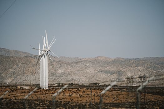
Wind turbines divide into two main architectures: Horizontal Axis Wind Turbines (HAWT) and Vertical Axis Wind Turbines (VAWT), and the architecture choice cascades through tower, foundation, and control-system specs on the production line [S3]. HAWTs dominate utility-scale capacity planning because their three-blade upwind rotor sweeps a larger swept area per unit of structural mass, which directly raises the capacity factor that the planning formula is built around [S3].
VAWTs accept wind from any direction without a yaw drive, which simplifies site civil works but typically delivers a lower capacity factor on the same wind resource, so they tend to show up in distributed-generation or urban-edge applications rather than in multi-hundred-MW capacity plans [S3]. For a greenfield production line, the planning decision is less about generator topology and more about whether the rated-capacity and CF assumptions match the architecture the line will actually build [S1][S3].
Reference Turbine Power Curve: Locking the Rated-Capacity Input
Installed capacity in a spatial plan is calculated from technical characteristics of a single reference wind turbine — its hub height, rotor diameter, and rated power — then multiplied by the number of non-overlapping footprints that fit inside the suitable zone [S2]. Two constraints govern how tightly turbines can be packed: rotor-diameter spacing rules of thumb in the prevailing wind direction (commonly 5–7 rotor diameters) and perpendicular row spacing (commonly 3–5 diameters) to limit wake losses [S2].
Wake losses inside a cluster can shave 5–15% off the single-tower CF, so the rated capacity in the planning formula should be discounted for downstream rows, not applied as if every turbine saw free-stream wind [S2]. Planners also feed measured or reanalysis wind data at hub height into the reference turbine's power curve to back out a site-specific annual energy yield, and only that adjusted yield enters the CF formula [S2].
Comparison: Planning Criteria Across HAWT, VAWT, and Reference-Turbine Method

Three planning approaches line up against the criteria that drive a defensible capacity number: HAWT-based utility planning, VAWT-based distributed planning, and the reference-turbine GIS method used in published spatial studies [S1][S2][S3]. On typical onshore CF, HAWT sites sit higher than VAWT sites on the same wind resource because swept area per unit mass is larger [S3]. On spatial gating, the GIS reference-turbine method is the only one of the three that explicitly combines Delphi, linear, and geometric AHP weighting with constraint overlays to produce a buildable-hectare count [S2].
On planning-formula transparency, the HAWT and reference-turbine methods both plug straight into CF = (Annual Energy Yield / (Rated Capacity × 8760)) × 100, whereas VAWT planning often substitutes per-unit-area yield metrics because nameplate per tower is lower [S1][S2][S3]. For a production-capacity decision, the reference-turbine GIS method is the option that ties the CF formula, the spatial constraint stack, and the architecture choice into a single auditable output [S2].
Failure Modes and Spec Pitfalls in Capacity Plans
The most common failure in a capacity plan is mixing units: feeding rated capacity in MW into the CF formula while the script expects kW inflates the denominator by a factor of 1000 and crashes the result to near zero [S1]. A second failure is quoting polygon area instead of buildable area after constraint overlay, which overstates the number of installable turbines and feeds back into an inflated installed-MW headline [S2].
A third failure is using free-stream wind speed in the reference power curve without subtracting intra-cluster wake losses, which lifts the modelled CF above what the plant will actually deliver in year one of operation [S2]. A fourth is hard-coding 8760 h when the planning horizon is a leap year (8784 h) or when downtime for scheduled maintenance is subtracted from the denominator — the constant must match the accounting window, not the calendar by default [S1].
Standards, Sourcing, and Engineering References
Capacity planning work should anchor on the Burton et al. Wind Energy Handbook treatment of capacity factor and reference-turbine power curves, which is the standard citation in the GIS-based wind siting literature [S2]. Brazilian wind atlases (Atlas eólico: Rio Grande do Sul, the Brazilian Wind Potential Atlas from MME) are the working source for hub-height wind data when siting in that region, and they are publicly downloadable from the cited ANEEL and Eletrosul repositories [S2].
For the CF formula itself, the MATLAB File Exchange submission "Wind Turbine Capacity Factor Calculation" (Version 1.0.0, 1.2 KB, 97 downloads, 5.00/5 over 13 reviews, dated 1 Aug 2023) is a working reference implementation, and a capacity plan that cannot reproduce its single-line CF calculation against a stated rated capacity and annual energy yield is not ready for sign-off [S1]. The script's only required inputs — annual_energy_yield in kWh and rated_capacity in kW — define the data contract a planning team must hand to a production line, and any deviation from that contract is a spec gate, not a stylistic choice [S1].
For a parallel look at how the same spec-first discipline applies across a wind-turbine manufacturing equipment vendor map, see the Wind Turbine Manufacturing Equipment Guide: Vendor Spec Map 2026 reference, which lines vendor capability against rated-capacity ranges in the same MW class. Where capacity planning must interface with process instrumentation, the turbine flowmeter and pressure transmitter encyclopedia entries cover the sensor specs typically called out in nacelle and hydraulic test benches. A useful contrast to the HAWT/VAWT split — different equipment class, same spec-first selection logic — sits in the concrete batching plant vs concrete vibrator selection map, where rated capacity, cycle time, and a CF-equivalent utilisation factor are the gating inputs.
Component reference pages worth checking: flow meter.