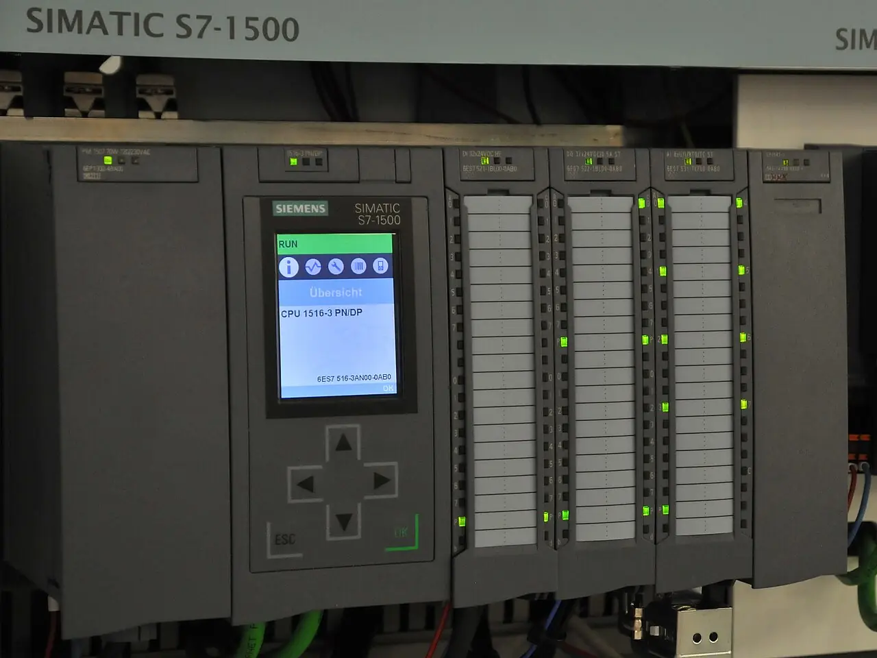
A flow computer is a dedicated, certified computation device that stands between a meter run and the accounting system: it collects raw pulses from the primary flow meter, frequency and serial data from a coriolis flowmeter, pulse trains from a turbine flowmeter or an oval gear flow meter, or the differential reported by a differential pressure transmitter across an orifice plate flowmeter run, together with pressure and temperature inputs, and converts them into corrected volumes, mass, and energy at contract conditions using standard calculation algorithms. The computation itself is the certified product: the algorithm versions, the audit trail, and the sealed configuration are what distinguish it from general automation hardware doing arithmetic. In gas field language the same class of device is called an EFM, for electronic flow measurement, and the two names describe one duty.
Procurement engineers meet these devices at custody transfer and fiscal points: pipeline receipts and deliveries of crude and refined products, natural gas sales and allocation metering, LPG loading, refinery loading racks, tanker terminals, and in cheaper allocation form, plant steam and utility balancing. The decision this page settles is whether the metering point needs a certified flow computer at all, which calculation pack applies, liquid API MPMS or gas AGA, and what audit, retention, and area classification requirements the RFQ must write so the accounting department and the auditor accept the totals. Every chapter feeds one specification block: streams, inputs, algorithms, certifications, and the interfaces to the skid around it.
This page treats the flow computer as a purchasing object: which inputs and calculation packs a metering point needs, what API 21.1 and the AGA reports actually require the device to do, how proving updates a meter factor, what the audit trail must retain, and how streams, certifications, and hazardous area interfaces combine into an RFQ a supplier answers with hardware and firmware versions. It is written for engineers who issue purchase specifications, not for readers who want a brochure summary.
Chapter 1 / 06
What a Flow Computer Is and What Is Being Decided
The definition has teeth. A flow computer is not a box that displays a rate; it is a device whose arithmetic is traceable to published measurement standards, whose configuration is sealed against silent change, and whose records are organized so that a third party can audit what happened months later. It totalizes pulses against a K factor, applies correction equations that turn line conditions into base conditions, applies the meter factor from the last proving, and stores the result in tamper evident logs with a real time clock stamp. That last clause is the commercial heart of the product: custody transfer totals move money, and the device exists so that both parties to the money can trust the number without trusting each other.
What is actually being decided in this purchase is where computation is allowed to live. A modern PLC can sample pulses and run arithmetic fast enough; a DCS can host a function block that approximates the corrections. The flow computer is bought when the calculation must carry certified provenance and an audit seal rather than a programmer's initials: the algorithm implementations are tested and versioned against API and AGA documents, the housing carries tamper switches, the configuration changes are logged events, and the whole package holds a measurement certificate, API 21.1 compliance for electronic gas measurement in North American gas practice, or MID and OIML R117 context for liquid metering in Europe. The RFQ decision is therefore not performance, it is evidentiary standing: whether the totals from this point will be defended in an accounting reconciliation, and to which standard.
The naming deserves one paragraph because it confuses procurement. EFM, electronic flow measurement, is the gas field term for the same device class, and "gas flow computer" and "liquid flow computer" usually differ only in firmware pack and I/O population. The batch controller at a loading rack is a different duty with a family resemblance: it stops a preset quantity into a truck compartment, where the flow computer accounts for what left the rack. The two meet in loading systems, where the batch logic fires valves and the fiscal totals land in the flow computer. A gas chromatograph is not a flow computer either, but it feeds one: heating value from the GC arrives over Modbus and the flow computer multiplies corrected volume by energy content to report energy, the unit many gas contracts actually settle.
The honest accuracy position frames everything that follows. The computation error of a certified flow computer is negligible, 0.01 percent class on totalization, while the primary flow meter contributes 0.2 to 1 percent or more depending on technology and proving discipline. The device is bought to protect and correct a measurement, not to create one; money spent here without money on the meter run and its proving is misspent. What the buyer is really purchasing is the certainty that a 0.5 percent meter stays 0.5 percent after corrections, configuration events, clock stamps, and an audit are applied to it.
The station around the device decides half the order. Inputs arrive as pulses over shielded cable, sometimes through a signal conditioner that squares up turbine pickup coils; analog 4 to 20 mA loops from a pressure transmitter and a temperature transmitter; direct RTD inputs for critical temperature; and serial Modbus RTU or TCP streams from multivariable transmitters and analyzers. Outputs go to SCADA, to a pipeline host, to valve control in skid duty. In hazardous areas the field wiring lands through approved barriers or the whole device sits in an Ex d enclosure. Chapter 4 prices these rows; chapter 6 wires them.
Chapter 2 / 06
How the Calculation Engine Works
Everything starts at the inputs. Pulse inputs are counted against a K factor, pulses per unit volume, entered per meter run and sealed as a configuration event; typical cards accept 0 to 10 kHz with scalable amplitude thresholds, and serious streams are wired dual channel, two independent counters on the same pickup, so that a lost or extra pulse is detected as a mismatch instead of entering the totals silently. A turbine flowmeter and an oval gear flow meter both arrive this way, as pulses whose unit value is known from proving. A coriolis flowmeter may deliver frequency pulses for mass or volume, or higher resolution values over Modbus. The orifice path is different: a differential pressure transmitter, a static pressure transmitter, and a temperature input feed the AGA 3 equation set directly, and the device integrates flow from those live values rather than from counted pulses.
The liquid path is gross to net. Volume counted at line conditions is corrected to base conditions using API MPMS Chapter 11.1: the temperature correction factor CTL and the pressure correction factor CPL, computed from measured temperature and pressure with the fluid properties in the standard. Multiply gross volume by CTL and CPL and the result is net standard volume, the number a crude oil contract settles. Where a density meter or a coriolis density output exists, mass follows directly; LPG and light hydrocarbon service often settles in mass for exactly this reason. The meter factor from the last proving multiplies in as a sealed correction, and every application of a new factor is an audit event with a timestamp and an author.
The gas path is a stack of AGA documents. AGA 3 computes flow from an orifice run: differential, static pressure, temperature, bore, and plate geometry into mass flow. AGA 7 covers linear meters, turbine and rotary positive displacement, driven by pulse inputs with compressibility applied downstream. AGA 8, the detail characterization method, computes the compressibility factor from gas composition or agreed properties; AGA 10 provides complementary methods for other gas applications; a full composition from a chromatograph lets the device use AGA 8 detail properly instead of a generalized correlation. AGA 9 governs multipath ultrasonic custody metering where an ultrasonic flowmeter is the primary. Energy reporting multiplies corrected volume by heating value, per the contract unit, and AGA 5 frames that energy computation context. The firmware names these algorithm versions in the configuration record; the RFQ should name them too.
Recording discipline is what API 21.1 actually regulates for electronic gas measurement. The device accumulates flow on fixed intervals, hourly and daily records being the settlement norm, logs unaccounted time when inputs are invalid under defined rules, and stores configuration changes, alarms, and events in a sealed audit log. Retention is concrete: API 21.1 expects at least 35 days of onboard configuration and event records, and serious devices hold far more, with battery backed real time clocks, 5 to 10 year battery life typical, keeping timestamps honest across power loss. Totals live in nonvolatile memory so a supply failure costs history of milliseconds, not months. Communications use store and forward buffering: when the SCADA link drops, the device keeps recording and backfills the host on reconnect.
The arithmetic closes with checks the buyer rarely sees until they matter. Square root extraction on differential, low flow cutoffs, pulse validity windows on dual channels, input range and rate alarms, and watchdog supervised execution all sit under the certified firmware. The result is a computation error around 0.01 percent of total, an order of magnitude below any field meter, which is why the metering skid budget belongs on the primary and its proving, and the flow computer budget on features, certifications, and audit depth rather than on chasing decimal places.
Chapter 3 / 06
Types, Construction, and Duty Boundaries
The catalog divides by stream count, firmware pack, and area rating. Single stream units meter one run and are the tank truck and small skid standard. Multi stream units host 2, 4, 8, or more runs in one chassis, sharing the display, communications, and audit subsystem, which is how a pipeline station meters six meter tubes with one certified device and one clock. Allocation class units trade custody certificates for price and live inside plants on steam, water, and fuel gas balancing. The EFM flavor packages the same gas math in a field housing with solar and battery options for remote wells. Combined liquid and gas firmware exists and suits terminals that load both, at the cost of a longer validation conversation with the metering authority.
Hardware follows metering room practice rather than panel fashion. Power is redundant, dual 24 V DC feeds or AC with DC backup, diode auctioneered, with a watchdog that alarms on either supply failing. Totalizers and configuration live in nonvolatile memory; the real time clock rides a lithium battery specified for 5 to 10 years of retention. Enclosures are DIN rail or rack format in control rooms, or stainless and composite field housings with convection cooling, ambient ranges of roughly minus 40 to 60 deg C for outdoor work. Displays are segment LCD or graphic, and every serious unit keeps a local display because commissioning a meter run without one is misery.
Communication is layered. Modbus RTU over RS-485 remains the field lingua franca to transmitters and chromatographs; Modbus TCP and Ethernet carry the same registers to SCADA faster; digital I/O runs valve commands, proving signals, presets, and alarms; and printer or serial ports survive at loading racks. Where a remote PLC hosts skid logic, the flow computer remains the totalizing authority: the PLC sequences valves, the certified device counts and corrects. On the input side, noisy turbine pickups over long runs go through a signal conditioner before the pulse card, and intrinsically safe field loops land through a safety barrier appropriate to the gas group, or the whole instrument wears Ex d explosion proof certification with sealed cable entries.
The duty boundaries are worth writing down. This is not a batch controller: it accounts, it does not sequence valves to a preset fill, though the two cooperate at loading racks. It is not a gas chromatograph: composition arrives from the analyzer, the flow computer consumes it. It is not a general purpose controller and should not be bought as one; a site that needs PID loops should buy a PLC for the loops and let this device do measurement. And it is not where money should be saved on a custody point: the price difference between an allocation unit and a certified custody unit is small against a single month of disputed volume on a large line.
Configuration class
Streams
Typical duty
Hardware notes
Single stream fiscal
1
Tank truck loading, small custody point, LPG skid
Compact DIN or field housing, one pulse card, Modbus RTU
Multi run station
2 to 8 or more
Pipeline metering stations, terminal headers
Shared display, audit, and comms; per run pulse and analog cards
Allocation class
2 to 8
Plant steam, water, fuel gas balancing
Simplified certificates, lower cost, no custody seal scope
EFM gas field unit
1 to 4
Remote wells, tap stations without mains power
Solar and battery power, cell or radio host links, RTU habits
Combined liquid and gas
2 to 8
Terminals loading both product families
Dual firmware packs, longer validation scope with authority
Chapter 4 / 06
Key Specification Parameters
The datasheet rows below decide whether a quoted unit can actually serve the metering point. The paragraphs after the tables cover the two rows auditors read first, algorithm identification and audit retention.
Attribute
Typical range or options
What it decides
Streams supported
1 to 8 or more meter runs per chassis
Station architecture: one device or many
Pulse inputs
0 to 10 kHz scalable, K factor per run, dual channel
Which meters connect directly and lost pulse detection
Analog and RTD inputs
4 to 20 mA with HART options, direct RTD channels
Pressure transmitter, temperature transmitter, DP wiring
Calculation packs
API MPMS 11.1, API 21.1, AGA 3, 5, 7, 8, 9, 10
Which fluids and contracts the totals can settle
Computation accuracy
0.01 percent class totalization
Confirms the meter, not the computer, dominates error
Audit and retention
Sealed event log, 35 day minimum onboard, months typical
API 21.1 standing and audit defensibility
Real time clock backup
Battery 5 to 10 years, timestamps across outages
Trust in interval records and event order
Communications
Modbus RTU and TCP, Ethernet, digital I/O, serial
SCADA host, chromatograph, and skid integration
Power
Redundant 24 V DC or AC with diode backup
Total continuity through single supply failure
Environment and rating
Minus 40 to 60 deg C class, Ex d or Ex ia options
Outdoor installation and hazardous area acceptance
Certification scope
API 21.1 EGM, MID and OIML R117 context, ATEX or IECEx
What the metering authority and contract will accept
Algorithm identification is the row that makes totals defensible. A compliant device does not merely implement AGA 8; it implements a stated implementation of it, and the configuration record identifies the algorithm and version used for every interval. The RFQ should require the vendor to state, per calculation pack, the standard, the implementation version, and the validation evidence, because "AGA 8 compliant" without a version is a phrase, not a specification. The same logic applies to liquid packs: API MPMS Chapter 11.1 has implementation editions, and the two parties to a custody transfer should be running the same one or should agree in the contract which applies.
Audit retention decides what an auditor can reconstruct. The requirement to write is straightforward: sealed configuration and event logging with tamper detection, at least 35 days of onboard records per API 21.1 with a preference for devices holding months, battery backed clock through outages, store and forward buffering on communication loss, and an export format the host or an audit tool can read without the vendor present. The table below compresses the calculation standards into the form a specification section can carry.
Standard
Domain
What the device does with it
API MPMS Chapter 11.1
Liquid volume correction
Computes CTL and CPL factors, gross to net standard volume
API MPMS Chapter 21.1
Electronic gas measurement
Interval records, unaccounted rules, event logging, 35 day retention
AGA Report 3
Orifice metering
Computes flow from differential, static pressure, temperature, geometry
AGA Report 7
Turbine and rotary meters
Pulse based volume with correction factors applied
AGA Report 8
Gas compressibility
Detail characterization from composition for accurate density
AGA Report 10
Gas properties
Complementary compressibility and property methods
AGA Report 9
Custody ultrasonic
Governs multipath ultrasonic flowmeter measurement applied to totals
AGA Report 5
Energy measurement
Frames the conversion of volume and heating value into energy
OIML R117 and MID
EU liquid metering
Accuracy class and conformity scope for legal metrology acceptance
Close the specification with the document list: algorithm versions per pack, type certificates for the area rating, the factory calibration and firmware checksum procedure, and the retention depth actually fitted. A quotation that cannot name the algorithm implementation versions is answering a different question than the one the RFQ asked.
Chapter 5 / 06
Selection Decision Factors and RFQ Language
The decision sequence runs as a checklist, and each step eliminates a class of quotations before price comparison begins.
State the duty honestly: custody, allocation, or check metering, and name the governing contract standard the totals must satisfy.
Count the streams and the meter technologies on them, then size the chassis and the pulse, analog, and serial cards from that list.
Pick the calculation packs: API MPMS 11.1 and 21.1 for liquid and gas settlement, AGA 3, 7, 8, 10 as the gas metering requires.
Define the audit scope: sealed events, retention depth, export format, and who is allowed to change configuration under which procedure.
Fix the proving interface: prover signals, meter factor entry as a sealed event, and the proving cadence the contract expects.
Resolve the area classification: Ex d enclosure or Ex ia loops with a safety barrier per gas group, and name the certificate.
Plan integration: Modbus registers for the host, digital I/O to the skid PLC, chromatograph and analyzer links, and store and forward depth.
Require the documents: algorithm versions, type certificates, firmware checksum practice, and battery replacement schedule.
Against neighboring computation platforms the honest map runs as follows, and it belongs here rather than in the page title. A PLC can count pulses and apply corrections with good code, and sites do it for internal flows; what the general purpose PLC does not carry is certified algorithm provenance, a sealed audit trail, and measurement certification, which is exactly why fiscal points do not use one. A DCS hosts the supervisory layer beautifully and remains the wrong home for the certified totals. The batch controller is the mirror image at a rack: it lands a preset quantity into a compartment and hands the fiscal accounting to the flow computer that shares the same pulses. A gas chromatograph feeds the energy computation rather than performing it. The flow computer occupies the narrow ground where arithmetic becomes legally defensible measurement.
Meter pairing drives the I/O list, and the pairings repeat across the industry. A turbine flowmeter delivers clean pulses at 0 to 10 kHz class and wants dual channel counting plus periodic proving. An oval gear flow meter does the same for LPG and viscous products at lower rates. A coriolis flowmeter hands over mass directly, by pulse or Modbus, and makes the density question disappear. An orifice plate flowmeter run with a differential pressure transmitter, a pressure transmitter, and a temperature transmitter is the classic AGA 3 station, fully computed in the device. An electromagnetic flowmeter feeds pulse or frequency for water and conductive product loading. An ultrasonic flowmeter, in multipath custody form under AGA 9, reports over serial with its own diagnostics. A vortex flowmeter covers steam and gas allocation duty from pulse inputs. None of these pairings constrains the vendor list; all of them constrain the card count.
The small end of the flow world deserves one honest sentence: a gas mass flow controller meters and controls small gas doses in laboratories and pilot plants, but it is a dosing instrument and never a custody device; a gas mass flow controller belongs at the bench, while totals that move money come from the meter and computer pairing above. Where the flow meter population is mixed and growing, buy the chassis with spare card slots; retrofitting streams into a full unit costs a second device.
The application table turns the pairing logic into the form a project file carries.
Application
Configuration to specify
Check before order
Crude pipeline custody station, 4 runs
Multi run chassis, API MPMS 11.1 pack, prover interface
Meter factor entry as sealed event, retention depth, host registers
Natural gas sales metering, orifice runs
Gas pack with AGA 3, 8, 10, chromatograph Modbus input
Algorithm versions in contract, energy unit per the sales agreement
Gas turbine meter lateral
AGA 7 pulse pack, dual channel counting
K factor provenance, proving cadence in the operating procedure
LPG loading rack
Single or dual stream, mass settlement via density input
Coexistence with batch controller preset logic, Ex rating of rack
Refinery products loading, 8 stands
Multi stream liquid unit, digital I/O to rack PLC
Card count with two spare slots, export format for the ERP
Water based additive loading
Single stream liquid unit, pulse input from an electromagnetic flowmeter
Conductivity window of the products, skid grounding
Plant steam allocation
Allocation class unit, vortex flowmeter pulse inputs
Honest accuracy statement: allocation, not custody, certificates
Remote well EFM
Solar powered field unit, radio host link
Store and forward depth against worst link outage, battery schedule
Custody check meter
Second independent chassis on the same run
Separate power and signal paths so one fault cannot bias both
The RFQ block should be written once and reused: number of streams and duty class; meter technologies with pulse, analog, and serial counts; calculation packs with implementation versions; audit scope with retention depth and export format; proving interface and meter factor procedure; area classification with certificate basis; power redundancy; communications to host and skid including a safety barrier schedule where applicable; environment; and the document list. A quotation returned without algorithm versions or retention numbers is incomplete at any price.
Chapter 6 / 06
Installation, Standards, Failure Modes, and Maintenance
Signal wiring decides the first year of reliability. Pulse and analog cables are shielded twisted pair, grounded at one end, routed away from power circuits, and kept within the vendor length tables; turbine pickups over long runs get a signal conditioner near the meter to square the coil output before transmission. Surge protection goes on every field cable that leaves the skid, because the most common hardware failure in the field is not the computer, it is an input card killed by a nearby lightning induced surge on a long line. Multi point grounding, shared neutrals, and convenient but wrong cable shortcuts account for most commissioning noise tickets; the fix is discipline, not filtering.
Hazardous area installation follows two accepted routes. Explosion proof, Ex d, puts the certified enclosure and sealed cable glands at the hazardous location and keeps the wiring method strict. Intrinsically safe, Ex ia, keeps energy out of the field loop entirely: each loop passes through a safety barrier mounted on the safe side, the barrier entity parameters match the field device, and the loop documentation lives in the inspection file. Mixing the two philosophies on one skid is common and fine; mixing them on one loop is not. The RFQ should state the gas group, temperature class, and certificate basis, and the verifier will find the barriers on the drawing or they do not exist.
Commissioning and proving give the device its numbers. Configuration is entered under procedure and sealed: K factors, fluid properties, algorithm selections, contract units. Proving runs the meter against a prover, ball or small volume, and the resulting meter factor is entered as a sealed event with an author and timestamp; between proofs, the factor stands. The real time clock is checked against a reference at every proof, because interval totals inherit clock error. Analog inputs are ranged and checked against calibrated sources, orifice impulse legs are proven filled, and dual channel pulse counters are verified against each other with the meter flowing. The commissioning record, configuration listing, and first audit log export are filed together; that bundle is what an auditor asks for first.
Failure modes are few, known, and mostly detected by the device itself. Pulse input failure announces as a dual channel mismatch or a dead counter, and the totals flag unaccounted time per API 21.1 rules instead of guessing. Communication loss to the host triggers store and forward; the buffer depth against the longest credible outage is a selection number, not a comfort. Power failure exercises the redundancy and, on total loss, the nonvolatile totals and battery clock; restoration is an event in the log. Real time clock drift accumulates quietly between proofs and is corrected on the proof schedule, which is one reason the schedule exists. Surge damage presents as one dead input channel after a storm, which is why chapter wiring budgeted the protectors. Firmware faults are rare and are managed by version control: updates on custody devices follow procedure, checksum verification, and a log entry, never a casual download.
Maintenance is calendar driven and cheap next to what it protects. Review the audit and alarm logs monthly for unaccounted time and input faults. Prove meters on the contract cadence, common practice monthly to quarterly for liquid custody, and enter factors under seal. Replace RTC batteries on schedule, typically every 5 years well inside the 10 year retention claim, and verify the clock at every proof. Exercise and inspect surge protectors after electrical storms, check barrier continuity annually where Ex ia is used, and keep one cold spare of the chassis or at least the I/O cards for single stream sites. Export and archive the configuration and logs off device on a fixed cycle; retention onboard is a floor, not an archive strategy. The file that leaves this maintenance loop, factors, proofs, clock checks, and log exports, is the evidence that keeps the next contract negotiation short.
FAQ
What separates a flow computer from a PLC running flow math?
Certified provenance and audit standing. A PLC can count pulses and apply correction equations accurately, but it carries no certified implementation of the API MPMS or AGA algorithms, no sealed configuration event trail, no measurement certificate, and no tamper evident housing. A flow computer is built so its arithmetic can be defended in a custody dispute: algorithm versions are recorded, changes are logged events, and the device holds type approval. Use the PLC for control and let the certified device own the totals.
When is AGA 8 used and when is AGA 10 applied?
AGA Report 8, the detail characterization method, computes gas compressibility from a full or agreed composition and is the default for custody metering where accuracy pays. AGA Report 10 provides complementary property and compressibility methods suited to other gas applications and operating ranges. In practice the firmware selects the method from the composition data available: chromatograph analysis feeds AGA 8 detail, while agreed standard properties may run a generalized route. The RFQ should name which method and implementation version settles the contract.
What does API 21.1 actually require of the device?
API MPMS Chapter 21.1 governs electronic gas measurement: flow accumulated on fixed intervals, hourly and daily records being the settlement norm, defined unaccounted time rules when inputs go invalid, sealed configuration and event logging with tamper detection, and at least 35 days of onboard record retention. It expects battery backed timekeeping and auditable totals. Devices typically exceed the retention floor, but the floor is the compliance line. Ask the vendor to state the retention depth fitted and the export format, because auditors read both.
What is meter proving and what is a meter factor?
Proving runs the meter against a known volume from a ball or small volume prover at operating conditions. The ratio of true volume to indicated volume becomes the meter factor, entered into the flow computer as a sealed, timestamped event with an author. Raw totals then carry that factor until the next proof. For turbine and positive displacement meters this discipline is what holds custody accuracy, and the factor history doubles as the meter health record, predicting bearing or rotor wear.
What happens to totals when power fails?
Totals live in nonvolatile memory and survive full power loss, and the real time clock rides a battery specified for 5 to 10 years of retention. Redundant supplies, dual 24 V DC feeds with diode auctioneering or AC with DC backup, alarm on either leg failing so the outage is an event, not a discovery. On restoration the device logs the power event and resumes; interval records show the gap per the unaccounted rules rather than interpolating invented volume. Nothing about the failure corrupts the audit trail.
Is an EFM the same device as a flow computer?
For practical procurement, yes. EFM stands for electronic flow measurement and is the gas field name for the same device class, usually packaged in a field housing with solar power and radio or cellular host links for remote wells. A gas flow computer and a liquid flow computer differ mainly in firmware pack and I/O population, not in principle. The selection question is duty class, custody versus allocation, plus the calculation packs and certifications, regardless of which name the catalog uses.
How are flow computers wired in hazardous areas?
Two accepted routes exist. Explosion proof, Ex d, installs the certified enclosure with sealed glands at the hazardous location. Intrinsically safe, Ex ia, limits loop energy so the field circuit cannot ignite: each loop crosses a safety barrier on the safe side, entity parameters match the field devices, and the loop documentation stays in the inspection file. State the certificate basis, gas group, and temperature class in the RFQ. Many skids mix Ex d computers with Ex ia instrument loops, which is acceptable while no loop mixes the two.