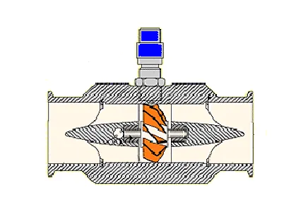
A paddle wheel flow meter is a velocity type liquid flow sensor whose rotor is a small paddle wheel, mounted either as an insertion probe through the pipe wall or inside an engineered tee, with its axis perpendicular to the flow. Magnets embedded in the rotor pass a Hall effect sensor or an induction coil in the sensor body, generating a pulse train whose frequency is proportional to liquid velocity. Dividing that frequency by the sensor's K-factor, stated in pulses per liter or gallon, yields volumetric flow, which makes the device a cheap, repeatable, and easily networked instrument for clean, water-class liquids.
Procurement engineers meet these sensors on irrigation laterals and pivot mains, on cooling tower make-up and blowdown lines, in water treatment dosing trains, and on chilled water and glycol loops, everywhere the liquid is clean, the viscosity water-like, the velocity inside the 0.3 to 6 m/s window, and the accuracy requirement at the 1 to 2 percent of reading level rather than fiscal metering class. The decision this page settles is whether the duty really sits inside that envelope, and if it does, which mounting style, wetted materials, and output type belong in the RFQ line set; if it does not, the honest output is a different technology, named in the selection chapter with the numbers that justify the switch.
This page treats the paddle wheel flow meter as a purchasing object: how the rotor and pickup turn velocity into frequency, how the K-factor converts frequency into volume and why it shifts with line size, what the mounting styles and wetted materials decide, and how the duty boundaries of clean liquid and modest accuracy are checked before an RFQ is issued. It is written for engineers who buy instruments, not for readers who want a brochure summary.
Chapter 1 / 06
What a Paddle Wheel Flow Meter Is and What Is Being Decided
The family resemblance comes first. The lead diagram on this page shows an inline turbine flowmeter, a machined body with an axial bladed rotor supported on bearings and a pickup above it; the paddle wheel is that architecture reduced to its economic minimum. Instead of a supported axial rotor, a small paddle wheel spins on a short shaft set across the flow, only partially immersed in the stream, and instead of a precision body, the sensor mounts through a tee, a saddle, or a hot tap fitting into whatever pipe the plant already owns. The shared physics, a rotor speed proportional to liquid velocity and a magnetic pickup reporting that speed as a frequency, is what makes both instruments pulse output devices with the same K-factor arithmetic; the difference is cost per point and the accuracy class that cost buys.
What is actually being decided in this purchase is narrower than the catalog implies. The paddle wheel is a monitoring instrument: 1 to 2 percent of reading accuracy on clean liquids, repeatability around 0.5 percent, and a velocity window of 0.3 to 6 m/s. Within that envelope it is the cheapest powered flow measurement per installed point, and the pulse output integrates cleanly into a PLC counter input or a bolt-on 4 to 20 mA transmitter head. Outside that envelope, in slurries, unscreened raw water, viscous chemicals, gases, or fiscal metering, it is the wrong instrument, and the purchase decision is really the admission that the duty sits inside the envelope or the selection of the technology that handles the duty outside it.
The boundary lines are worth naming early because they are absolute. Particles and fibers jam the rotor: a paddle wheel on an unscreened line is a maintenance subscription, not an instrument. The liquid must be single phase; entrained air bubbles read as flow the pipe never carried, and gas slugs spin the rotor erratically. The line must run full, because a partially filled pipe puts the paddles in air for part of each revolution. And the measurement is of velocity at the rotor, converted to volume by the pipe area, so the pipe internal diameter and the upstream flow profile must be known and controlled; a sensor quoted for one bore and installed in another is simply mis-calibrated from the first pulse.
The standards context sets the ceiling honestly. Municipal water meters in fiscal service are type evaluated under ISO 4064 and OIML R49, with pattern approval classes and periodic verification, and no paddle wheel sensor holds that status. The instrument is bought against manufacturer specifications, verified by water calibration at the factory and by field commissioning checks, and its certification lives in the K-factor document that must be filed with the instrument loop. A buyer who needs billing grade totals knows from this paragraph that the technology is excluded; a buyer who needs operational totals, dosing verification, and leak detection at the lowest cost per point has found the right page.
The purchase package, when the duty qualifies, is small enough to specify completely: sensor with wetted materials matched to the liquid, mounting style matched to the pipe, output matched to the controller, the K-factor certificate, and the straight run spool that gives the rotor an honest velocity profile. The chapters that follow give each of those five items its numbers, and the selection chapter names the neighboring technologies, with the accuracy and cost position of each, so the RFQ goes out once, to the right vendors, with the right line items.
Chapter 2 / 06
How the Rotor and Pickup Turn Velocity into Frequency
Mechanically the sensor is a paddle wheel, typically four to six blades molded around a hub with permanent magnets, spinning on a short shaft. Premium constructions use sapphire or ceramic sleeve bearings against a stainless or ceramic shaft, a pairing chosen for hardness, low friction, and indifference to water chemistry; commodity constructions use polymer bearings that work on clean cold water and wear quickly in anything abrasive. The rotor sits in the flow with its axis perpendicular to the pipe axis, so each blade is driven across a chord of the stream, and the wheel turns at a rate set by local liquid velocity, with the magnet poles sweeping past the pickup once per blade passage.
The pickup is the first spec decision, and the two families behave differently. A Hall effect sensor is a powered semiconductor device that detects each passing magnetic pole and issues a clean square wave; it works from zero velocity upward, tolerates slow rotation, and needs a supply, commonly 5 to 24 VDC, delivered over the sensor cable. A variable reluctance coil pickup, the same construction used on many a turbine flowmeter, generates its own voltage as the magnet sweeps the coil: no power at the sensor, excellent noise immunity in its band, but a self generated signal that weakens at low speed, so the usable frequency floor sits higher. Both deliver the same product: a frequency proportional to velocity, one pulse per blade passage per revolution, that the controller counts.
The K-factor converts frequency to volume, and its arithmetic is the whole calibration of the instrument. For an inline tee sensor, the factory measures the K-factor in pulses per liter or pulses per gallon in the tee's engineered channel and certifies it with the body; flow rate equals frequency divided by K, so a certificate stating 45 pulses per liter means a 90 Hz signal is 2 liters per second, about 7.2 cubic meters per hour, a velocity near 1 m/s in a DN 50 bore. For an insertion sensor, the wheel measures point velocity, so the volumetric K-factor depends on the pipe it is inserted into: pulses per unit volume equal the velocity response divided by the pipe's internal cross sectional area, which means the same sensor reads a different pulses per liter in DN 100 than in DN 200, and the K must be recalculated whenever the internal diameter changes. The worked number: at 2 m/s in a DN 100 pipe with a 100 mm bore, flow is about 56.6 cubic meters per hour, and at the 0.3 m/s window floor it is about 8.5; the sensor reports velocity faithfully, the pipe geometry sets the volume.
Accuracy and repeatability are separate purchases of credibility. Accuracy of 1 to 2 percent of reading, the honest class for this family, presumes a fully developed velocity profile entering the rotor, which is why every manufacturer specifies straight run, generally 10 pipe diameters upstream and 5 downstream, free of elbows, valves, and pumps. Repeatability around 0.5 percent is what makes the instrument useful in control: a dosing loop or a leak detection threshold can be tuned against a sensor that reads the same value for the same flow, even when that value carries a 1 to 2 percent bias. The error grows near the 0.3 m/s floor, where bearing friction and coil signal strength, on reluctance types, both degrade the response, and sizing the meter to live in the middle of the 0.3 to 6 m/s window is part of the purchase.
The output chain is where the sensor meets the plant. The native output is a pulse train, an open collector transistor contact on Hall types, wired over shielded cable to a counter input on the PLC or a dedicated totalizer; frequency is proportional to flow, so the count is the volume and the rate is available by timing. The alternative is the transmitter head: a local converter that turns the pulse train into a 4 to 20 mA current signal proportional to flow rate, the input most controllers and scada systems already carry, often with a local display and totalizer added. Pulse suits long cable runs and exact totals; current suits rate loops and retrofit panels, and many heads give both, which is worth specifying at order since adding it later means reopening the loop.
Temperature matters at the margins of the physics. Viscosity rises as liquid cools, and a glycol mix that metered well at 20 deg C drags the rotor at 2 deg C, shifting the K-factor slightly and justifying winter commissioning checks; a thermowell near the meter, feeding the temperature record to the controller, lets those shifts be explained rather than argued about. Plastic sensor bodies, the economic core of the family, cluster around 0 to 100 deg C service with pressure ratings near 10 bar at 20 deg C, derating with heat; stainless tee bodies extend temperature and pressure at the cost of the wetted-material simplicity that makes the plastic versions cheap. The derate curve belongs in the datasheet, and the operating point should sit comfortably inside it, not on the line.
Chapter 3 / 06
Types, Construction, and Duty Boundaries
Three mounting styles cover the family. The inline tee replaces a spool piece with an engineered tee whose internal channel is shaped around the rotor, factory calibrated as a unit; it is the accuracy and stability leader, standard from DN 15 to DN 50, and the default wherever new piping is being built. The insertion sensor slides through a threaded boss, a saddle, or a hot tap fitting so the paddle reaches the flowing stream without cutting the line out of service; it is the economic leader on large lines, quoted from DN 50 up to DN 600, and its accuracy depends on the care taken with insertion depth and the pipe's internal dimensions. The saddle mount is the insertion family's retrofit variant, bonding or bolting onto existing pipe, common on irrigation mains and station laterals where the alternative is a shutdown.
Wetted materials are chosen against the liquid from a short list. Body and tee materials: polypropylene for cost on plain water, PVDF for chemical resistance across a wide pH range, stainless steel for temperature, pressure, and plant standard compliance. Rotor: PVDF or polypropylene carrying the embedded magnets. Shaft and bearings: stainless shaft with sapphire or ceramic sleeve bearings on premium units, polymer bearings on commodity ones. Seals: fluorocarbon or EPDM O-rings matched to the liquid, and here is where dosing applications are won or lost, because a sensor body that survives the carrier water can still be destroyed by the concentrated chemical it doses; the compatibility check is written against the dosed concentration, not the diluted mix. For viscous oils and polymers the paddle wheel is simply out of its class, and that duty belongs to an oval gear flow meter, whose positive displacement rotors meter viscosity the paddle cannot.
The construction differences express the same trade from both ends. An inline tee buys a calibrated flow path and pays with a pipe cut; an insertion sensor buys a no-shutdown installation and pays with a K-factor that must be computed from the pipe's real internal diameter, which on old cast iron is rarely the nominal one. Plastic bodies buy cost and chemical resistance and pay with pressure and temperature ceilings; stainless bodies buy ratings and pay with the wetted parts list getting longer. Every row of the selection is that trade, stated with numbers, and the buyer who knows which side of each trade the duty lives on writes a two page RFQ instead of a twenty page negotiation.
Duty boundaries, stated bluntly. The paddle wheel meters clean, water-like liquids only: particles and fibers jam the rotor, and the screen that prevents it must exist upstream, be maintained, and be specified with the meter or the installation is incomplete. The liquid must be low viscosity, water-class, roughly water to light glycol, with manufacturer derating applying beyond; heavy fluids both drag the wheel and shift the K-factor. Once the liquid carries solids or the line cannot be interrupted, an electromagnetic flowmeter with no moving parts takes the duty at a price the selection chapter quantifies, and there is no upgrade path within the paddle family that changes that boundary. Gases are outside the family entirely: the rotor needs liquid density to spin against, and a paddle wheel in a gas line reads noise.
The table below consolidates the boundaries into the form a specifier scans before writing the RFQ.
Service
Suitable construction
Construction to avoid
Irrigation pivot and pump station mains, DN 50 to DN 300
Insertion sensor on saddle with upstream screen, surge protected pulse line
Unscreened raw water with sand; unprotected long cable runs
Cooling tower make-up and blowdown
Inline tee DN 25 to DN 80, pulse to totalizer, scale tolerant schedule
Blowdown with loose scale flakes and no strainer
Water treatment dosing verification
PVDF tee with 4 to 20 mA head, compatibility checked at full concentration
Commodity polymer bearings in abrasive dosed slurries
Chilled water and glycol energy monitoring
Stainless tee, sapphire bearings, thermowell pair for delta T
Plastic bodies on lines with pressure surge and water hammer
Screened secondary effluent reuse
Insertion after fine screen, cleanout access, quarterly rotor inspection
Any paddle installation on unscreened flow
Sludge, stock, and raw well water with grit
Not this family; electromagnetic flowmeter without a rotor
Every paddle wheel option, without exception
Chapter 4 / 06
Key Specification Parameters
The specification table lists the datasheet rows that decide whether a quoted sensor matches the duty. Each row is answered with a number or a named material, and the paragraphs after the table expand the rows vendors most often blur.
Attribute
Typical range
What it decides
Pipe size coverage
DN 15 to DN 600 across the family
Which mounting styles exist for the line
Velocity window
0.3 to 6 m/s
Minimum measurable flow and the stability of the K-factor
Accuracy
1 to 2 percent of reading
Fitness for monitoring, dosing totals, and leak detection
Repeatability
about 0.5 percent
Suitability for control loops and batch verification
Straight run
10 diameters upstream, 5 downstream
Whether the accuracy claim survives the installed piping
Wetted materials
PP or PVDF body and rotor, 316 shaft, sapphire or ceramic bearings
Chemical compatibility, bearing life, temperature exposure
Temperature rating
0 to 100 deg C plastic bodies typical
Sensor placement against hot sources and stored lines
Pressure rating
about 10 bar at 20 deg C plastic, derated; higher in steel tees
Hot tap viability and surge tolerance
Output types
open collector pulse, Hall or coil; 4 to 20 mA head optional
Controller interface: PLC counter input or analog loop
Supply voltage
5 to 24 VDC for Hall electronics
Power and cable planning for the point
K-factor certificate
pulses per liter or gallon, per stated bore
Totalizer setup and recalibration when the diameter changes
The K-factor row is the calibration of the instrument and deserves its own paragraph. Demand the certificate with the body, stating pulses per liter or gallon and the conditions, bore and velocity range, under which it was established; file it with the loop documentation, because the number is unique to the sensor body and, for insertion types, to the pipe it was computed for. When an insertion sensor moves to a different line or a lining change alters the bore, the volumetric K-factor must be recomputed from the new internal diameter, and the PLC scaling updated to match; an unupdated scaling factor is the most common self-inflicted error in the family, and it is invisible until a bucket test or a tank drawdown exposes it.
The output row decides the wiring and the controller budget. A pulse output feeding a PLC counter input is the exact-total configuration: every pulse is a counted volume increment, and rate comes from timing, which suits totalizing duties like cooling tower make-up accounting and irrigation allocation. The 4 to 20 mA transmitter head suits rate duties, dosing loops, and retrofit panels where an analog input already exists, and adds the local display many operators rely on. Where the loop alarms on flow loss, a hard wired flow switch remains the dependable backup on unattended stations: the PLC can derive low flow from a silent pulse train, but a dedicated flow switch with dry contacts closes independently of the counter card and the program behind it. Line pressure telemetry completes the point instrumentation on remote stations, where a pressure transmitter on the pump discharge separates a blocked strainer from a dry sump before a truck roll.
The mounting comparison below compresses the type decision into one table. The accuracy column quotes the honest class, not the catalog asterisk, and the K-factor column states whose geometry defines the calibration.
Mounting style
Typical sizes
K-factor basis
When chosen
Inline tee, calibrated spool
DN 15 to DN 50
Factory certified in the engineered channel
New piping and best accuracy demand
Insertion, threaded boss or hot tap
DN 50 to DN 600
Velocity constant divided by actual pipe area
Large lines and retrofit without shutdown
Saddle mount insertion
DN 80 to DN 600
Same as insertion, saddle sets insertion depth
Existing mains where cutting is refused
Accessories close the specification. A strainer or screen upstream, sized to the particle load the line actually carries, is part of the meter purchase, not an optional extra, because it protects the rotor the meter depends on. Surge protection belongs on long outdoor cable runs, and a thermowell adjacent to the meter, with the temperature signal recorded, gives the maintenance engineer the context for viscosity driven K-factor shifts on seasonal glycol duties. Naming these in the RFQ keeps them in the quotation instead of in the punch list.
Chapter 5 / 06
Selection Decision Factors and RFQ Language
The decision sequence runs as a checklist, and each step either confirms the paddle wheel or hands the duty to a named neighbor.
Write the liquid honestly: water, glycol percentage, dosed chemicals at full concentration, and the particle and fiber load after screening. This single line decides wetted materials or disqualifies the family.
Compute the velocity range from real flows and real internal diameter, and confirm it sits inside 0.3 to 6 m/s with normal duty mid window, not at the floor.
Check the straight run against the piping as drawn, 10 diameters upstream and 5 downstream; if the run does not exist, budget the spool or accept the error.
Choose the mounting by pipe size and shutdown permission: inline tee to DN 50, insertion or saddle above, hot tap where the line cannot stop.
Fix the output by controller: pulse to a counter input for totals, 4 to 20 mA head for rate loops, both where the budget allows.
Order the K-factor certificate with the body and compute the insertion scaling from the measured bore, not the nominal one.
Specify the protective package: strainer, surge protection on long runs, and the commissioning verification, bucket test or tank drawdown, that proves the scaling.
Accept the accuracy class in writing: 1 to 2 percent of reading, repeatability about 0.5 percent, monitoring grade, and if the requirement is fiscal, stop here and change technology.
Against the neighboring technologies, the comparison belongs in this selection chapter, and it runs on cost per point against accuracy and dirt tolerance. The turbine flowmeter shares the rotor and pickup physics in a machined axial body and delivers accuracy near 0.5 percent on clean lubricating liquids, at several times the price and with strict filtration demands; on large water lines it is rarely the economic choice, and on skid hydrocarbon duty it is the standard one. The oval gear flow meter takes the viscous oils, polymers, and chemicals beyond the paddle viscosity ceiling, metering by positive displacement with no reliance on velocity profile, and paying in pressure drop and wear on abrasive liquids. The electromagnetic flowmeter is the standard answer once solids or unscreened water enter the duty: no rotor to jam, a lined spool with electrodes, requiring only liquid conductivity above roughly 5 microsiemens per centimeter, and priced well above a paddle point but far below the cost of chronic maintenance on a jammed rotor.
The ultrasonic family brackets the paddle from both directions. A transit time ultrasonic flowmeter in a spool delivers better inherent accuracy on clean full pipes and holds calibration without wetted moving parts, at a multiple of the paddle price; where the pipe cannot be cut at all, a clamp on ultrasonic flow meter reads from the outside, trading setup care and some accuracy for zero contact, and the clamp on ultrasonic flow meter is justly the survey instrument on district cooling and retrofit surveys. Where mass or density is the real measurement, a coriolis flowmeter reads mass directly at custodial accuracy, priced per line at a level that confines it to skids and fiscal points rather than irrigation laterals. The vortex flowmeter earns its keep on steam, condensate, and gas service where the paddle cannot work at all, needing only a high enough Reynolds number to shed cleanly. An orifice plate flowmeter survives where differential pressure instrumentation already exists and modest accuracy with easy audit trails is enough, paying permanently in permanent pressure loss. The variable area flowmeter still wins the panel wall when an operator wants local visual flow with zero power and zero electronics, and it remains the commissioning cross-check of record on small lines. The paddle wheel takes the wide middle ground: water class liquids, monitoring grade accuracy, the lowest installed cost per point, and pulse integration that the modern control system already speaks. When the fluid or the accuracy contract changes, the choice collapses quickly: a coriolis flowmeter appears on skids where mass is the commercial unit, a vortex flowmeter on steam and gas headers the paddle cannot enter, an orifice plate flowmeter where differential pressure taps already exist, an ultrasonic flowmeter where wetted parts are unwelcome, and a variable area flowmeter where the reading must be seen by eye at the wall.
The application table pairs the common duties with the construction that survives them and the check that belongs in the order file.
Application
Construction to specify
Check before order
Irrigation pivot monitoring
Insertion DN 50 to DN 200, screen, surge protection, pulse to PLC
Screen mesh against sand load, cable route and lightning exposure
Cooling tower make-up totalizing
Inline tee DN 40 to DN 80, 4 to 20 mA rate plus pulse total
Scale flake filtration, freeze protection on outdoor runs
Water treatment chemical dosing
PVDF tee, isolated outputs per skid, concentration checked materials
Compatibility chart against full strength chemical
Chilled water energy monitoring
Stainless tee with sapphire bearings, thermowell pair for delta T
Glycol concentration effect on K-factor and viscosity
Screened reuse water flow
Insertion with cleanout access and quarterly inspection plan
Screen reliability and the maintenance window behind it
Sludge and unscreened raw water
Electromagnetic flowmeter; no rotor sensor survives this duty
Conductivity of the liquid for the liner and electrode choice
The RFQ block should be written once and reused. A complete block reads: quantity and line size with schedule and material, plus measured internal diameter where a lining exists; liquid with glycol percentage or chemical concentration, temperature range, and screened particle load; minimum, normal, and maximum flow with the corresponding velocities; required accuracy and repeatability with the duty named, monitoring, totalizing, or control; mounting style with straight run availability stated; wetted materials for body, rotor, shaft, bearings, and O-rings; output type, pulse or 4 to 20 mA, with supply and cable length; K-factor certificate requirement and scaling responsibility for insertion types; accessories, strainer, surge protection, display; and the commissioning verification method and acceptance band. A quotation returned without the K-factor certificate or with a wetted materials answer of one word is incomplete at any price, and sending it back once trains the vendor file for every later point.
Chapter 6 / 06
Installation, Standards, Failure Modes, and Maintenance
Installation begins with position and profile. The meter goes where the straight run lives, 10 pipe diameters of undisturbed flow upstream and 5 downstream, with the line guaranteed full: on up-flowing vertical runs or horizontal runs under consistent pressure, never on a drain line that runs part full. Insertion sensors mount with the alignment pin or flow arrow facing upstream and the paddle at the depth the K-factor computation assumed, which is why hot tap installations specify the insertion dimension on the drawing. The tap for an insertion sensor is made through a full port valve with the line either depressurized or hot tapped by procedure, and the sensor is seated and locked per the manual; a paddle at the wrong depth in an unknown profile is calibrated by hope. Wiring follows pulse discipline: shielded cable, the shield grounded at one end, separation from power cables, and surge arrestors on any run that crosses open ground, because irrigation fields are lightning country and counter inputs are unforgiving.
Commissioning proves the scaling, and the methods are deliberately crude and effective. A bucket test on small lines, timing a known volume against the totalizer, or a tank drawdown or pump curve cross-check on large ones, verifies the complete chain, sensor, K-factor, PLC scaling, and display, against physical reality; an acceptance band of a few percent against the meter class is the pass line. Record the raw frequency at a known stable flow and file it, because the maintenance engineer comparing that frequency a year later has the fastest possible diagnosis of rotor drag: same flow, lower frequency, fouled or dragging rotor. The pressure transmitter on the station, where one exists, gives the strainer differential story, and the thermowell record explains any seasonal K-factor drift on glycol duty; commissioning is where those baselines are captured, while everything is new and someone is paid to watch.
Standards frame what the instrument is and is not. ISO 4064 and OIML R49 define the metrology classes for fiscal water meters, and their pattern approval regime is exactly what a paddle wheel does not hold, which is why the family is specified for operational rather than custody measurement. The manufacturer's water calibration and the K-factor certificate are the factory evidence; the field verification methods above are the owner's evidence. Electrical installation follows the plant's area classification rules where they apply, and the low voltage DC nature of the sensor keeps that burden light. None of this exempts the buyer from the honest datasheet: a vendor accuracy statement without the velocity range and straight run conditions attached is not a specification, and the RFQ should say so.
Failure modes follow a short, well understood list. Rotor jam by particle or fiber, the signature failure, announced by a frozen pulse count on a running pump; the screen, its condition, and the cleanout procedure are the entire countermeasure. Ferrous debris collection: the rotor magnets attract iron filings from the line, the deposit drags the wheel, and readings drift low long before they stop; cleaning the rotor restores the K-factor, which is why scheduled cleaning beats breakdown maintenance on any line with history of weld bead or pipe scale. Bearing wear: the wheel spins stiffly, frequency falls at constant flow, and the baseline frequency record catches it early; sapphire and ceramic sleeves extend the interval by years on abrasive histories. Dry running: bearings and shaft score quickly without liquid, so pumps that can run dry need protection, and the hard wired flow switch or a low flow alarm derived in the PLC shuts the point down. Entrained air: bubbles spin the wheel fast without volume, over-reading flow that never existed, fixed by air separation and correct line filling upstream. Electrical: long unshielded runs pick up noise that counter cards count as flow, fixed by cable discipline, and lightning takes unprotected field electronics in one storm, fixed once, expensively, by the surge arrestor that was optional at order.
Maintenance scales with the dirt load and is scheduled from the baseline record. On screened clean water, an annual verification against a known volume and a visual rotor inspection are the whole program. On reuse water and outdoor irrigation, quarterly inspection and cleaning match the screen duty, with the K-factor verified after every cleaning, because a cleaned rotor is a re-calibrated rotor only if the verification says so. O-rings and the sensor seal are replaced whenever the sensor is withdrawn, and the withdrawal is the natural moment to re-mark insertion depth and re-check the alignment pin. Keep one spare sensor and its certificate per station type on the shelf, and the mean time to repair for this family falls to the time it takes to close a valve and swap a body, which is the operational argument that balances the modest accuracy class: the instrument is cheap, honest about its limits, and back in service the same afternoon.
FAQ
What accuracy can I expect from a paddle wheel flow meter?
Plan on 1 to 2 percent of reading on clean, water-like liquids inside the specified velocity window, with repeatability around 0.5 percent. That is ample for monitoring, dosing verification, and batch totals, but it is not custody transfer metrology: billing and fiscal measurement require meters type evaluated under ISO 4064 or equivalent, which paddle wheel sensors are not. Read the accuracy statement together with its velocity range, since error grows near the 0.3 m/s floor.
What liquids suit a paddle wheel sensor?
Clean, low viscosity liquids: municipal and irrigation water, cooling tower and chilled water circuits with glycol, and dosed chemicals below the manufacturer's viscosity limit, water-like service with published derating above. Sand, fibers, and stringy solids jam the rotor and destroy bearings, so unscreened raw water and sludge lines need a different technology named in the selection chapter of this page.
What straight run does the installation need?
Ten pipe diameters of straight, undisturbed run upstream and five downstream, free of elbows, valves, and pumps. The sensor measures local velocity, so a distorted profile from a close coupled elbow reads as flow error that no K-factor corrects. Where the run cannot be provided, budget the error, add the spool piece, or choose an averaging technology instead of hoping.
How does the pulse output become a flow rate?
Divide frequency by the K-factor. If the certificate states 45 pulses per liter, a 90 Hz signal is 2 liters per second. Feed the pulse train to a PLC counter input or local totalizer, or order the 4 to 20 mA transmitter head and let the conversion happen inside the sensor. Keep the K-factor certificate with the loop file, because the number is unique to the body and, for insertion types, to the pipe bore it was computed for.
Should I choose an insertion sensor or an inline tee?
Choose the inline tee where the pipe can be cut and best accuracy matters: the engineered channel carries a factory calibrated, stable K-factor. Choose the insertion sensor on large lines, DN 100 upward, where a tee costs more than the meter and hot tap installation keeps the line in service. Recalculate the insertion K-factor whenever the pipe internal diameter changes, including relining, and verify by bucket test or drawdown after any change.
Can this meter be used for billing or custody transfer?
No. Paddle wheel sensors are monitoring instruments with 1 to 2 percent of reading accuracy, while fiscal water measurement requires meters type evaluated under ISO 4064 and OIML R49 with pattern approval and periodic verification. Use the paddle wheel for operational totals, leak detection, and control, and install a pattern approved meter where money changes hands.
How do I keep the rotor from jamming?
Screen the flow. A strainer upstream, fine enough to stop the particles the line actually carries, prevents most jams, and scheduled inspection catches the rest before a breakdown. Embedded rotor magnets collect ferrous debris over time and drag readings low, so clean the rotor at intervals and verify the K-factor afterward. Never let the sensor run dry: sleeve bearings fail quickly without liquid, and dry running protection belongs in the control scheme.