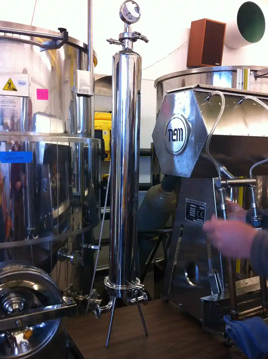
A heater treater is a pressure vessel that breaks crude oil and water emulsions with heat and then separates the stream into clean crude, produced water, and gas, typically standing at the tank battery between the production separators and the storage tanks. In its classic form a horizontal or vertical steel shell holds a fire tube, a u-shaped bundle burned with produced gas, that raises the emulsion to treating temperature; coalescing sections and weirs give water droplets time and surface to unite and fall; and a gas boot or separator section at the top takes the vapors. Electric variants replace or supplement the fire tube with electrodes that impose a high voltage field across the settling section, coalescing water droplets in stubbornly stable emulsions.
This page treats the heater treater as a purchasing object: how oil gravity and emulsion severity set the treating temperature, how retention time and vessel geometry set throughput, how fire tube heat flux and burner selection set the fuel draw, and how interface control, relief, and flame arrest keep a vessel full of hot oil and gas on the safe side. It stands beside the three phase separator, which splits the same phases without heat, and ahead of the storage tanks whose sales crude it must deliver at pipeline basic sediment and water.
The decision concentrates in five places: the well stream and its emulsion behavior, the treating temperature and retention time the crude actually needs, the heating medium, fire tube or electric, interface control and water handling, and the vessel code, relief, and safety architecture a fired, gas-bearing pressure vessel carries. Get those right and the shell diameter, length, and burner duty follow.
Chapter 1 / 06
What a Heater Treater Is and What Is Being Decided
The machine exists because crude comes out of the ground as an emulsion. Water droplets stabilized by asphaltenes, resins, fine solids, and soaps from the formation resist the quiet settling that a plain separator offers: a three phase separator upstream will split the free water and the gas, but the residual emulsion, the milky bond of oil and water, holds together for hours or days on its own. Heat attacks that bond directly, viscosity falls, droplet mobility rises, and the stabilizing films soften; add retention time and coalescing surfaces and the droplets unite and fall until the oil meets its sales specification, commonly 0.5 to 1 percent basic sediment and water or better. The heater treater is the vessel that applies that combination continuously at the battery.
In the horizontal form, the dominant modern shape, the emulsion enters a gas separating section at the top, drops through to the heating section where it flows around the fire tube, rises through a spreader into a large settling section where oil and water separate across an interface held by a water leg or interface controller, and exits as clean oil over a weir while water leaves from the bottom and gas from the boot. The vertical form stacks the same duties in a taller, smaller-footprint shell: gas at top, heating in the middle around a vertical fire tube, settling below, with an external crude boot or integral section handling oil accumulation. Both are welded steel pressure vessels designed to a vessel code, fitted with a fired heater, and instrumented for level, temperature, pressure, and flame.
What is being decided, in purchasing terms, is five things. First the duty: how much emulsion at what water cut and what inlet temperature must reach what treating temperature. Second the time: how many minutes of settling this crude needs at that temperature, which sets vessel volume. Third the heat: fire tube fuel gas, electric power, or hot oil from elsewhere, and the flux and metallurgy of the tube that delivers it. Fourth the water and interface handling: dump valves, interface control, and where the produced water goes. Fifth the safety envelope: relief valves, flame arrest, burner management, and the codes a fired vessel holding live crude must satisfy. The paragraphs that follow work these in order.
A scale tour grounds the machine. A single-well battery runs a vertical treater the size of a large home water heater, 0.8 to 1.2 meters in diameter, burning a few thousand cubic meters of gas a month. A multi-well pad runs a horizontal vessel 3 meters across and 12 meters long. A high-water-cut heavy-oil facility runs trains of large horizontal treaters or electrostatic units ahead of storage. The physics is identical across the range: heat, time, and surface, traded against fuel and steel at whatever scale the lease demands.
Chapter 2 / 06
How Heat, Coalescence, and Retention Time Do the Work
Treating temperature is the master variable because every mechanism it drives is exponential. Raising crude from 30 to 60 deg C cuts viscosity roughly in half to a third, and settling velocity in the simplified Stokes sense scales inversely with continuous phase viscosity, so droplets fall twice to three times as fast; the stabilizing films around the droplets weaken with temperature, so coalescence becomes more likely at each collision; and the density contrast between oil and water widens slightly, helping separation further. The practical result is the treating chart every producer knows: for a given crude, basic sediment and water falls steeply with temperature until it flattens at some crude-specific point, and the economic treating temperature sits just where the curve bends, because every degree above it burns fuel for nothing.
That bend is crude-specific and must be found by test. Heavy asphaltenic crudes and stable chemical emulsions may want 70 to 90 deg C; light paraffinic crudes often treat at 40 to 55 deg C; waxy crudes add their own constraint, the pour point, above which the oil must stay to move at all. The bottle test in the lab and, better, a witnessed field trial on the actual well stream with the actual chemical demulsifier tell more than any catalog. The specification should state the design treating temperature with its basis, the emulsion test behind it, and the turndown range the vessel must handle, because production declines and water cuts rise over the life of the lease.
Retention time is the second half of the trade. After heating, the emulsion needs minutes in a quiet zone for droplets to collide, coalesce, and settle; typical designs give 10 to 40 minutes of oil residence in the settling section depending on crude gravity and emulsion severity. More time means bigger steel; more heat means smaller steel and a bigger fuel bill, and the optimum vessel is sized at the point where another meter of shell costs more than the fuel it saves. The coalescing internals, spreader plates, parallel plates, and packing in some designs, shorten the required time by giving droplets surfaces to unite on, and they are worth specifying where footprint is tight.
The fire tube delivers the heat with a discipline all its own. A u-shaped or serpentine assembly of welded pipe, usually submerged in the emulsion at the vessel bottom, carries an industrial burner firing produced gas; heat flux on the tube surface is held to a design maximum, commonly in the 20 to 35 kilowatt per square meter class, because emulsions foul and coke on overheated steel and a coked tube burns out from the inside. The burner management system lights and monitors the flame, a flame arrester protects the gas line, and the stack or vent handles the combustion products. Electric heat replaces the tube with resistance elements or inserts the electrodes of an electrostatic field; both remove the open flame at the price of power infrastructure.
Interface control holds the whole machine together. The oil water interface in the settling section must stay between limits: too high and water carries over into the sales oil, too low and oil leaves with the produced water. A simple water leg, a vertical standpipe set to the right height, holds it hydraulically; an interface controller reading the interface and driving a control valve on the water dump does it actively and is the modern norm, the arrangement every operator with a slug-prone well should pay for. Either way the produced water leaves to disposal or cleaning, the clean oil tops the weir to storage, and the gas boot relieves vapors to the vapor line or flare. Around it all stand the level transmitter, the temperature transmitter on the heating section, a pressure transmitter, and the relief hardware a coded vessel demands.
Chapter 3 / 06
Horizontal, Vertical, and Electrostatic Designs and Duty Boundaries
The horizontal heater treater is the workhorse of multi-well batteries and anything with throughput. Its long settling section gives a large oil water separation area, which is what throughput actually buys, and its fire tube sits in a dedicated heating compartment where flow is directed across the tube for even heat. Sizes run from roughly 1 to 3 meters diameter and 6 to 15 meters length, treating flows from tens to thousands of cubic meters of emulsion per day. The horizontal shape handles foaming and gas slugs from upstream better than the vertical, and its horizontal fire tube is easier to remove for repair.
The vertical heater treater serves small batteries and tight pads. Its footprint is a circle rather than a rectangle, its gas separating section sits naturally on top, and the emulsion heats as it descends around the fire tube before rising through the settling section into an oil boot. Verticals treat lower flows, commonly single-well or low-volume multi-well duty, and they stack nicely beside a two phase separator and the storage tanks in the classic battery arrangement. Their limitation is settling area: throughput per unit of steel is lower, and the interface has less room to absorb upsets.
The electrostatic treater adds a high voltage field to the settling section. Electrodes above the heating zone impose tens of thousands of volts across the flowing emulsion; water droplets polarize, attract, coalesce, and fall far faster than gravity alone allows, which cuts the required residence time and the vessel size for a given duty. Electrostatic coalescing earns its capital on tight, stable emulsions, heavy crudes, and desalting service where salt removal matters, and it appears both as integral electrode sections in heater treaters and as the dominant mechanism in crude desalters at refineries. The trade is electrical infrastructure, insulator maintenance, and a control philosophy that must interlock power with level, because energized electrodes in air rather than emulsion arc.
Duty boundaries against the neighbors deserve plain language. The heater treater is not a three phase separator: the separator splits free gas, free oil, and free water without heat and sends the stable emulsion onward, and most batteries run both in series, separator first, treater second. It is not a fired heater: the fired heater raises process fluid temperature for refinery duty with no phase separation at all, a different machine sharing only the word fired. It is not an oil water separator in the api or cpi sense: those clean produced or wastewater streams of free oil at ambient conditions. And where the emulsion is not really an emulsion, where the water separates free in a bucket test in minutes, the treater is overkill and the answer is a separator plus time.
Design
Typical size range
Where it wins
Watch-outs
Horizontal fire tube
1 to 3 m diameter, 6 to 15 m long
Multi-well throughput, settling area
Footprint; tube removal access for repair
Vertical fire tube
0.8 to 1.5 m diameter
Small batteries, tight pads
Lower throughput per steel tonne; upset sensitivity
Electrostatic (with heat)
Refinery and heavy crude class
Tight stable emulsions, desalting duty
Power and insulator upkeep; level interlocks
Hot oil or water bath variants
Site specific
No gas to burn, heat medium available
Indirect heat adds a loop and its losses
A paragraph on the electrostatic variant's discipline, because it fails differently from the fired one. The electrodes live in the settling section, and their health is an electrical maintenance story: insulators foul with paraffin and scale, transformer and control gear need dry housings, and the interlock philosophy must remove power before the level falls below the electrodes, because the field arcs in gas. There is no flame to supervise and no fire tube to coke, so the burner management chapter disappears, and with it the fuel gas line, the flame detector on the burner, and the stack; in its place stand the power feed, the voltage controls, and a different conversation with the electrical inspector. Sites weighing the two should also weigh the safety neighbors: a fired treater brings an open flame into a battery that also runs tanks and trucks, which is why the gas detector coverage around the vessel and the battery layout rules exist, and the electrostatic machine reads quieter on that ledger.
Chapter 4 / 06
Key Specification Parameters
The specification is built from the well stream outward. The process set states emulsion flow with water cut range, oil gravity and viscosity at treating temperature, inlet temperature, gas oil ratio, and the emulsion character, bottle test or field trial evidence of what temperature and time it needs. The performance set states outlet basic sediment and water for the oil and oil in water quality for the produced water if it matters downstream. The design set states treating temperature range, retention time basis, fire tube duty and flux, or electric power, vessel dimensions, and coalescing internals. The safety set states design pressure and temperature, vessel code, relief valve sizing basis, burner management requirements, and the flame arrest arrangement. The commercial set states fuel gas quality and availability, or power, and the materials for any sour service.
Parameter
Typical range
Why it matters
Treating temperature
40 to 90 deg C by crude
The master variable; sets fuel and vessel size together
Oil retention time
10 to 40 min
Settling volume and steel weight
Outlet bs and w
0.5 to 1 percent or better
The sales specification the vessel exists to meet
Fire tube heat flux
20 to 35 kW/m2 class
Tube life; coking limit on the emulsion side
Fire tube duty
50 kW to 2 MW class
Fuel gas draw and burner selection
Design pressure
35 to 100 bar sites vary
Vessel code, relief, and upstream tie-in
Interface control
Water leg or interface controller
Water carryover versus oil in water
Demulsifier dose
10 to 200 ppm typical
Chemistry that halves required temperature
Two lines in that table carry the project. Treating temperature carries it because it is simultaneously the fuel bill, the vessel size, and the risk: under-treat and sales crude fails the basic sediment and water test, over-treat and the fuel line, the vapor pressure of the stock tank crude, and the scaling in the water system all worsen. Fire tube flux carries it because it is the difference between a tube that lasts fifteen years and one that cokes and burns out in three; the flux number and the tube metallurgy, with velocities past the tube verified, are the two items on the vendor drawing worth arguing about.
Instrumentation completes the machine, and on a fired vessel it is safety, not decoration: level transmitters on oil and interface with high level shutdown, a temperature transmitter on the heating section with high temperature shutdown, pressure transmitter with high pressure shutdown, flame supervision on the burner through a proper management system, and a safety relief valve sized on the credible cases, fire and blocked outlet among them. The gas line to the burner carries a flame arrester and double isolation. Remote telemetry is standard on unmanned batteries, and the treater's signals, temperatures, levels, burner status, are the ones the pumper checks first every morning.
Chapter 5 / 06
Selection Decision Factors and RFQ Language
Selection starts with the emulsion, tested rather than assumed. A bottle test matrix on the actual well stream, several temperatures crossed with several demulsifier chemistries and doses, gives the treating curve and the chemical that bends it; a field trial on a rental treater confirms it at scale. From that curve the design temperature is chosen just past the bend, the retention time is read from the settling that succeeded, and the chemical program is specified with a dose rate and a fallback. Producers who skip this and size from a neighboring lease's numbers inherit vessels that either under-treat in February or burn gas all August for nothing.
The heating medium follows the site. Produced gas is the classic fuel: it is there, it has no better use at a remote battery, and the burner tolerates its quality swings with the right management system. No gas or tight emission limits push to electric heat, resistance elements where power reaches, or electrostatic designs that use power for coalescing rather than bulk heat; hot oil loops appear where a central facility serves multiple vessels. Fuel gas quality, hydrogen sulfide content and heating value swing, belongs in the RFQ because burner management and tube metallurgy both take their cues from it.
Vessel orientation follows throughput and pad geometry, with the horizontal earning its steel at higher flows and the vertical earning its footprint at lower ones. Sour service decisions, hydrogen sulfide partial pressure above the threshold, push materials to the sour service steels and hard-facing welds per the applicable sour service practice, and they belong in the RFQ as a stated condition, not a surprise discovered in the mill test report. Design pressure is chosen against the upstream separator settings and the gas boot arrangement so the treater never becomes the bottleneck that lifts the separators.
A complete RFQ states, on one process data page: emulsion flow and water cut range now and at end of life; oil gravity, viscosity at treating temperature, and pour point; inlet temperature and gas oil ratio; bottle test or trial evidence and design treating temperature; required outlet bs and w; retention time basis; available fuel gas analysis and pressure, or electric supply; design pressure and temperature and vessel code; sour service declaration; interface control preference; burner management and flame arrest requirements; and the ambient extremes including the winter that the water systems must survive. Vendors quoting against that page are quoting the same vessel, and shell sizes, tube duties, and fuel draws become comparable numbers.
Balance of battery belongs in the same decision. Upstream, the three phase separator or the free water knockout drum ahead of the treater takes the gas and the free water so the treater treats only the true emulsion; a properly sized flash tank or vapor line from the treater gas boot keeps vapors going somewhere safe; downstream, the produced water needs its disposal route and, increasingly, polishing before disposal, and the clean crude line runs to storage with a loading arm or lact unit at the tank. A treater bought without its battery context is a vessel sized for the wrong day-one stream and the wrong end-of-life one.
The transfer systems around the vessel decide whether its product actually arrives somewhere. Produced water leaving the treater at temperature carries oil and solids toward disposal or cleaning, and on long or hilly routes a progressive cavity pump, tolerant of gritty hot water, earns its maintenance reputation against the alternatives; clean crude to stock tank or sales usually moves by gravity or a small centrifugal pump at the battery, with the lact unit or tank gauging downstream closing the custody chain. Size these pumps for end-of-life water cut, not day one, because batteries water out as they age and the pump that was right at lease start becomes the bottleneck at year ten. The same forward-looking arithmetic applies to the gas boot line, which should be big enough for the vapor rate at the highest treating temperature the vessel will ever run.
Chapter 6 / 06
Installation, Standards, Failure Modes, and Maintenance
Installation is vessel work with a fired finish: foundations or skids, process and fuel gas tie-ins, the relief valve and its vent, burner commissioning with the management system proven through its shutdown tests, and instrument loops live before first heat. Initial operation brings the vessel up warm with water or clean crude before introducing emulsion, verifies the interface control actually holds the interface where the drawing says, and sets the treating temperature on the evidence of the outlet sample rather than on the chart. The first week of operator training on sampling and burner behavior is the cheapest reliability the machine will ever buy.
The governing references are vessel and burner practice plus the producer's own specifications. API Spec 12L historically covered vertical and horizontal emulsion treaters, and the API advisory dated January 2023 records its withdrawal from the monogram program, so the buyer cites the document's historical content where useful but leans on the vessel code, the burner management practice, and the surface facility engineering practice of the operator. Kimray and peers publish the applied guidance on heater treater operation and mechanical versus electric selection that field engineers actually use. Nothing replaces the bottle test, and no standard chooses the treating temperature for you.
Failure modes are thermal, chemical, and mechanical in that order of frequency. Under-treating, wet oil at the stock tank, means temperature short, chemical short, retention short, or interface wrong; the sample point and the temperature trend localize it in one inspection. Fire tube failure means coked or corroded steel, from over-firing, low level exposing tube, or sour water attack, and it is the outage that defines the machine. Scaling in the water sections, especially where the produced water is saturated, plugs dumps and legs. Interface upsets from slugs or control failure send water forward or oil backward. Each symptom has a small cause set, and the sampling discipline that catches them costs one valve and one bottle.
Symptom
Likely cause
First action
Wet oil at storage
Temperature, chemical, time, or interface short
Check treating temperature trend and burner firing; verify demulsifier pump; sample down the vessel to find the interface
Fire tube hot spot or failure
Coking from over-flux or low level
Reduce firing rate; verify level controls; pull tube for inspection at next downtime
Water dumps plugged or scaling
Scale in produced water sections
Chemical clean dumps and legs; check water chemistry; consider anti-scale dosing
Verify vent and boot lines clear; check pressure trend against separator settings
Routine maintenance is the discipline of fired vessels: burner tuning each season, flame scanner and management system checks, tube inspection by camera or entry at each turnaround, relief valve testing on its schedule, and the level and temperature transmitters calibrated so the shutdowns still trip when asked. The demulsifier program wants quarterly review against the bottle test, because wells change and the chemical that treated January will not treat June. Sand and solids accumulate in the bottom sections and are jetted or drained at each entry.
The institutional item is sampling, boring, daily, and decisive. A daily centrifuged sample of the outlet oil, trended against treating temperature and chemical dose, is the entire health record of the machine; it shows the seasonal bend before the tank fails the crude inspection, it shows the chemical losing effectiveness before the oil goes milky, and it shows the interface drifting before the water system chokes. The treaters that run fifteen years without drama are the ones whose operators sampled them every morning and wrote the number down.
Automation deserves the last word in maintenance because unmanned batteries are the norm now and the treater is the machine most worth watching. A small plc or remote terminal unit trending treating temperature, both levels, burner status, and dump activity gives the pumper a morning diagnosis instead of a surprise, and the same box runs the shutdown logic that was once relays. The sampling discipline still matters, but the trend is what turns a wet oil excursion from a tank problem into a same-day setpoint or chemical correction. Vendors now ship these packages instrumented and programmed; the buyer's job is to insist the point list matches the battery's telemetry and to keep the programs backed up with the drawings. The clean crude line runs to storage where a vapor recovery unit on the tank breaths and a level switch backup on the treater oil section are the two retrofits most batteries wish they had specified on day one.
FAQ
How does a heater treater differ from a three phase separator?
The separator splits free gas, free oil, and free water by gravity and residence time without adding heat, and the stable emulsion passes through it largely intact. The treater adds heat, coalescing internals, and controlled settling to break that emulsion, which is why batteries run the two in series: separator first to take the bulk phases, treater second to finish the oil.
What treating temperature does my crude need?
Only the emulsion itself can answer: the bottle test matrix across temperatures and demulsifiers, confirmed by a field trial, gives the curve of basic sediment and water against temperature, and the design point sits just past the bend where hotter stops helping. Light crudes often treat at 40 to 55 deg C, heavy asphaltenic crudes want 70 to 90 deg C.
Fire tube or electric heat?
Fire tube on produced gas where the gas exists: cheapest to run, simplest to understand, tolerant of remote sites. Electric where there is no gas or where emissions rules bite, and electrostatic where the emulsion is tight enough that a voltage field coalesces better than extra heat. The RFQ should price both when the site could go either way.
Why do fire tubes fail?
Mostly coking and corrosion: over-firing beyond the design heat flux plates emulsion solids and coke on the steel, which insulates it and lets the metal overheat, and low water level exposing the tube or sour water attack does the rest. The protections are a conservative flux number, level shutdowns that actually trip, and tube inspection at every entry.
How much demulsifier will I need?
Ten to two hundred parts per million by volume on the emulsion is the working band, found by the bottle test and confirmed by trend, not by the drum label. The chemical and the treater are one system: the right chemistry can cut the required treating temperature ten degrees, which is fuel saved every day of the lease.
What safety provisions does a fired treater carry?
A coded vessel with a properly sized safety relief valve, burner management with flame supervision and high temperature and high and low level shutdowns, a flame arrester on the fuel gas line with proper isolation, and vent routing that sends the gas boot somewhere safe. On unmanned sites, telemetry that reports those shutdown states to someone who will drive out.
When is a heater treater the wrong answer?
When the water separates free in minutes without heat, a plain separator plus retention does it cheaper; when the stream is refinery-scale and the duty is desalting, the electrostatic desalter is the machine; and when the fuel and the emissions budget cannot carry an open flame at all, the answer is electric heat or chemical treatment upstream. Test the emulsion before buying steel.