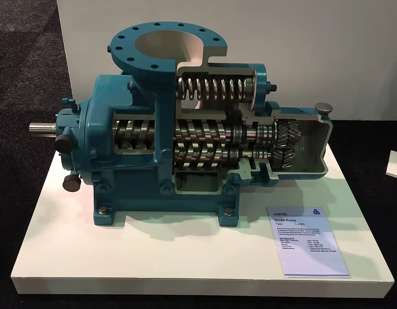
The progressive cavity pump is a single-screw rotary positive displacement machine: a helical steel rotor turning inside an elastomer stator molded with one lobe more than the rotor. The interference fit between the two forms sealed cavities that progress axially from suction to discharge, moving fluid steadily and without pulsation. Engineers reach for it when the medium is viscous, abrasive, shear sensitive, or loaded with solids, and the duty calls for low, repeatable flow at low to moderate pressure.
Commercial frames span roughly 0.01 to 100 m3/h of flow, differential pressure reaches about 24 bar in a 4-stage element and up to 48 bar in extended multi-stage builds, and viscosity is accepted to about 1,000,000 cP when the inlet is engineered to feed the screw. Because flow is a direct function of shaft speed, one pump covers a wide turndown band on a variable frequency drive, and metering repeatability follows without a separate controller.
This page decodes the geometry that sets flow per revolution, the stage count that sets pressure, the stator elastomer that sets chemical and thermal limits, and the drive and protection package that keeps the element alive. It closes with the failure modes a maintenance crew actually meets and the line items that belong in an RFQ.
The progressive cavity pump earns its place on viscous, abrasive, and solids laden duty that defeats most dynamic machines: sealed rotor-stator cavities carry 0.01 to 100 m3/h without pulsation, at up to 24 bar in standard elements. The chapters below give a specifier the geometry, the elastomer chemistry, and the datasheet lines that decide whether a unit runs 8,000 hours or fails in 800.
Chapter 1 / 06
What is a Progressive Cavity Pump
Definition and the job it does
A progressive cavity pump is a single-screw rotary positive displacement pump. A helical steel rotor with one external lobe turns inside an elastomer stator that has one internal lobe more than the rotor, the 1:2 geometry patented by Rene Moineau in the 1930s and unchanged in principle since. The rotor is ground slightly oversize for the stator bore, so the interference fit maintains a continuous seal line between the two parts at every angular position. That seal line divides the space between rotor and stator into closed cavities. As the shaft rotates, each cavity forms at the suction port, travels axially along the element, and releases at the discharge port. The fluid is carried, not thrown, and it leaves the pump at essentially constant rate with no valves anywhere in the wetted path.
The machine exists for media that defeat simpler ones. As viscosity rises above a few hundred cP, a centrifugal pump suffers falling flow, rising shaft load, and an NPSH margin that erodes toward zero, and at some thousands of cP it stops being a practical choice at all. A gear pump moves viscous clean liquids well, but hardened grit scores the meshing flanks and the close running clearances have no tolerance for solids. Within the wider screw pump family, twin and three spindle machines handle clean viscous oil at high pressure, at a precision and price level that abrasive sludge does not justify; the lead image on this page shows the cutaway of such a twin-screw sibling for comparison. The progressive cavity pump accepts solids to roughly 1/25 of the rotor diameter, moves water based slurry carrying 20 to 40 percent dry solids when hopper fed, and passes shear sensitive polymer floc largely intact because internal fluid velocities are low.
The commercial range runs from dosing frames moving a few liters per hour to hopper machines feeding filter presses at 60 m3/h. Differential pressure ratings reach about 24 bar in standard 4-stage elements and up to 48 bar in extended multi-stage builds, with each stage of element carrying 4 to 6 bar. Viscosity to about 1,000,000 cP is accepted when the feed arrangement is engineered for it. That envelope, plus pulse free delivery and speed proportional metering, is why the type dominates sludge, paste, and polymer duty across water treatment, mining, food processing, and chemicals.
When the selection question arises
The selection question arrives on predictable triggers. A thickened sludge line that a dynamic machine could once handle at 2 percent solids is uprated to 6 percent and the flow disappears. A dosing skid needs 10:1 turndown with repeatable delivery that a fixed speed machine cannot give. A filter press schedule demands one pump that fills fast, then presses slowly against rising pressure, then stops on a timer without dead heading. A food plant needs transfer that survives clean in place chemistry and steam. In every case the underlying decision is the same set of numbers: how much liquid per revolution the element must carry, how many stages the pressure needs, which elastomer the media chemistry tolerates, and what drive and protection hardware keeps the element alive.
What is actually being decided
Five purchases hide inside one pump order, and each is covered in its own chapter of this page:
Flow per revolution and the speed ceiling: the frame size, chosen so that abrasive duty runs at or below about 300 rpm (Chapter 2).
Stage count: differential pressure divided into 4 to 6 bar per stage, plus a margin stage on cyclic duty (Chapters 2 and 4).
Stator elastomer: the chemistry and temperature decision that sets stator life more than any other line (Chapters 3 and 4).
Drive: a gear motor with a variable frequency drive for turndown and controlled start torque, or fixed speed with a soft starter where turndown is not needed (Chapters 2 and 5).
Protection: dry run cutout and overpressure relief, without which the first operator error writes off the element (Chapter 6).
Get those five right and the pump is boring in the good sense: it runs for years between stator changes. Get one wrong and the failure modes catalogued in Chapter 6 arrive early, and most of them trace back to a specification line that was left vague at order time.
Chapter 2 / 06
Working Principle and Geometry
The Moineau principle and the sealed cavity
The geometry is asymmetric on purpose. The rotor is a single external helix of circular cross section; the stator is an internal helix with two lobes, molded so that the rotor pitch is half the stator pitch. Mounted on a fixed centerline the two would leave an open spiral passage and pump nothing. The rotor is instead driven on an eccentric orbit, held by the drive joint, and ground oversize so that at every angle metal presses into elastomer along a line. On the trailing side of that line the space between rotor and stator is a closed cavity; ahead of it, the previous cavity has just sealed off. One rotor revolution advances every cavity along the element by one stator pitch.
Cavity volume equals the free cross section between rotor and stator multiplied by the stator pitch. Multiply by the cavities passing the discharge per unit time and the result is flow, which is why capacity per revolution is the number that sizes everything else. Because the cavity is sealed along a moving line rather than opened and closed by hardware, there are no valves to stick, no ball seats to clog, and no sharp pressure spikes inside the element. Flow leaves the discharge close to constant: ripple is negligible next to the tooth meshing of a gear pump or the stroke cycle of a reciprocating metering machine.
Flow per revolution and the speed range
Manufacturers quote capacity as volume per 100 revolutions, because it lets a specifier compare frames independent of the speed any one vendor happens to quote. Small dosing frames carry about 0.5 L per 100 rev. Small transfer frames carry 2 to 10 L per 100 rev, mid frames 15 to 40 L, and large hopper machines several hundred liters per 100 rev. Delivered flow is capacity times speed times volumetric efficiency, and volumetric efficiency on a new element runs 0.90 to 0.97, declining as the stator wears. A frame rated 20 L per 100 rev running at 300 rpm therefore delivers about 60 L/min, or 3.6 m3/h, before slip is subtracted.
The working speed range is 100 to 600 rpm. Thin, clean, lubricating fluids run near the top of the band. Viscous transfer typically sits at 200 to 400 rpm. Anything abrasive belongs at or below 300 rpm, and the hardest slurries at 100 to 200 rpm. Speed is the wear dial: stator life falls steeply as peripheral speed rises, because the interference fit does the sealing and pays for it in friction. A useful planning figure is that halving speed on abrasive duty more than doubles stator life, which is why the worked example in Chapter 5 sizes the frame one step large and runs it slow rather than sizing tight and running fast.
Pressure, stages, and slip
Pressure capability is built by element length, not by wall thickness. One stage, meaning one stator pitch of element, carries about 4 to 6 bar of differential pressure. A 2-stage element rates 10 to 12 bar, a 4-stage element 24 bar, and extended elements reach 48 bar for heavy fuel and process duty. Slip is the leakage across the seal line from discharge back to suction: it rises with differential pressure, falls with viscosity, and grows steadily as the stator wears. Treat the per stage figure as a ceiling, not a target, and add one stage of margin on cyclic or high slip duty, because every pressure spike works the elastomer toward fatigue.
Suction behavior, dry running, and the drive train
The element is self priming and will lift when wet. Suction lift to 8.5 m is achievable on a wetted element with a stable suction line and no air leakage, though flooded suction is always the better installation. State the real suction condition in the RFQ, as flooded, static lift in meters, or suction head, because it changes the inlet recommendation and the dry run risk assessment. Dry running is prohibited absolutely: with no liquid in the element the interference fit generates friction heat with nowhere to go, and a stator can seize, char, or shed rubber within seconds to minutes depending on speed and preload. Chapter 6 covers the sensors and wiring that make this prohibition enforceable rather than aspirational.
The drive train exists because the pump wants low speed and high torque. Starting torque runs 2 to 4 times running torque, because the element must break static friction in the interference fit, and a cold viscous medium can add more. The standard package is a 4 or 6 pole motor through a gear reducer, or a direct drive low speed motor on small frames. Control is by a variable frequency drive: it gives a controlled ramp that limits start torque to what the joint and coupling can carry, a torque limit function that protects the element against a blocked line, and wide flow turndown with metering repeatability, because flow follows speed linearly. Where the duty is genuinely fixed speed, a soft starter performs the ramp and inrush function at lower cost, at the price of losing turndown and torque limiting.
Hopper feed and forced inlet variants
Dewatered sludge at 18 to 30 percent dry solids will not pour into a standard axial inlet, so the screw must be fed. Hopper variants mount the element under a rectangular or cylindrical hopper with an auger conveyor screw or forced feed chamber that pushes material into the cavities, often with a bridge breaker shaft or paddles to keep the hopper live. These machines run to 60 m3/h class at high solids and are the standard filter press feed unit in municipal dewatering plants. Specify hopper volume, auger drive power, and dry solids content together, because above roughly 25 percent dry solids the auger, not the pumping element, sets the achievable feed rate.
Chapter 3 / 06
Construction, Materials, and Duty Boundaries
The rotor: hard, plated, and precisely pitched
The standard rotor is hardened alloy steel of the AISI 4140 or 42CrMo4 class, hard chrome plated to a surface hardness of 60 to 65 HRC, with a chrome layer of 0.2 to 0.3 mm that can be reground and replated at service. Corrosive wetted duty moves to 316 class stainless, accepting a softer surface and faster wear when grit is present. Heavy abrasion duty moves to tool steel or powder metallurgy grades, sometimes with tungsten carbide coatings where the media justifies the cost. The rotor is the metering artifact: pitch accuracy sets flow calibration, so a 1 percent pitch error is a 1 percent flow error at every speed, and a scored rotor is a slipped calibration that no new stator will fix.
Rotor inspection at every service is quick and diagnostic. The chrome should be smooth and continuous. Circumferential scoring rings mark oversize grit passing through. Uniform matte wear along the sealing flank marks normal abrasive life and can be tolerated to the vendor limit. Localized burn marks near the suction end mark dry start events. Measure the rotor against the original drawing at each stator change, because a worn rotor chews a new stator at an accelerated rate and voids the arithmetic of your spares planning.
The stator: the elastomer is the pump
The stator is a molded elastomer sleeve bonded into a steel or stainless outer tube. Four commercial elastomers cover most duty, and they are selected on chemistry first, temperature second, abrasion resistance third. NBR nitrile is the default for water, sewage, and weakly acidic or alkaline water based media to 80 deg C; it swells in mineral oils and fuels and must be treated as a mineral oil free service compound. EPDM serves hot water and water based chemistry to 120 deg C and tolerates steam sterilization, which makes it the food and pharma choice, but any hydrocarbon, including assembly grease, attacks it. FKM serves mineral oils, fuels, aromatic solvents, and hot concentrated chemistry to 150 deg C, at 2 to 4 times NBR stator price and with noticeably poorer abrasion resistance. Natural rubber gives the best grit wear life on water based slurry at the lowest cost, and it has zero tolerance for oil films of any kind.
Hardness runs 40 to 80 Shore A. Softer compounds conform and seal better on thin liquids and slightly worn rotors; harder compounds hold their geometry longer on grit. The stator bore is molded undersize so the assembled element carries diametral interference of a few tenths of a millimeter to over a millimeter depending on frame size, and that interference, not any clearance, is what seals the cavity line. The full selection matrix with temperatures, media fit, and relative cost sits in Chapter 4 as a table, because it is a working specification tool rather than background reading.
Drive joints, shaft sealing, and the body
The rotor orbits as it rotates, and the drive joint absorbs that orbit. Pin joints are simple and cheap and suit small frames on clean duty. Universal or cardan joints suit mid and heavy duty and are greased on a schedule or sealed for life. Flexible drive shafts, which have no joint to wear or lubricate, suit food duty and moderate pressure. The joint is the second wear item after the stator: a worn joint lets the rotor orbit off center, the seal line breaks, and flow slips at pressure even with a healthy stator. Order the joint service kit with the first spare stator, not after the first joint failure.
Where the drive shaft passes out of the pressure casing, sealing options run from a packed gland, the adjustable and forgiving standard, to a single mechanical seal for sealed process duty, to a double mechanical seal with barrier fluid for abrasive, toxic, or flammable media. On sludge, the double seal with a clean barrier held 1 to 2 bar above pump pressure keeps grit out of the faces and is worth its premium. Casings are grey cast iron as standard, ductile iron at higher ratings, with a 316 stainless wetted path option for corrosive service. Flanges drill to EN 1092-1 PN10 or PN16 as the European default or ASME class 125 or 150 as the North American default, and food builds carry clamp ferrules instead.
Where the design stops being suitable
Solids size: grit larger than about rotor diameter divided by 25, meaning about 4 mm on a 100 mm rotor. Oversize grit scores the rotor and tears the stator; screen ahead of the pump or accept short element life.
Dry running: forbidden, with failure in seconds to minutes. If a dry start is credible on your installation, the dry run cutout is not an optional extra.
Dead heading: pumping against a closed discharge builds pressure until the stator ruptures or the drive trips, because the element cannot relieve itself. A relief valve or rupture disc belongs upstream of the first isolation valve.
Temperature: bounded by the elastomer, 80 deg C for NBR and natural rubber, 120 deg C for EPDM, 150 deg C for FKM, with short steam excursions only where the vendor allows them in writing.
Viscosity: about 50,000 to 100,000 cP on a standard inline inlet. Above that the feed, not the pump, governs delivery, and a hopper or forced feed machine is required.
Each boundary has a specification answer: a screen size, a sensor, a relief set pressure, an elastomer line, a feed design. Writing those into the datasheet converts every one of them from a waiting failure mode into a purchased line item.
Chapter 4 / 06
Key Specification Parameters
A progressive cavity pump datasheet can be decoded in five minutes once you know which lines carry the engineering and which carry the brochure. The table below lists the specification lines that matter, the typical ranges for commercial hardware, what each line actually decides, and how to state it in an RFQ so that competing vendors quote comparable machines rather than adjacent ones.
Specification line
Typical catalog range
What it decides
How to state it in the RFQ
Capacity per 100 rev
0.5 to 40 L, small to mid frames
Frame size; the true basis of comparison
Required flow at your stated rpm
Flow at duty
0.01 to 100 m3/h class
Duty point feasibility
Flow at duty viscosity, not at water
Max differential pressure
4 to 6 bar per stage; 24 bar standard; to 48 bar extended
Element length and price
Discharge minus suction, bar, static plus friction
Stage count
1 to 8 stages
Stator length, torque, cost
Stages for duty plus one margin stage
Max solids size
approx. rotor dia / 25, so 4 mm on 100 mm rotor
Screening and rotor scoring risk
Max particle mm and percent by weight
Viscosity range
1 to 100,000 cP inline; to 1,000,000 cP hopper
Feed design
Value at working temperature
Stator elastomer and temp
NBR 80, EPDM 120, FKM 150, NR 80 deg C
Chemical and thermal fit; stator life
Name the media, not just the elastomer
Rotor material
Hard chrome 4140; 316 stainless; tool steel
Corrosion and wear budget
Chloride level and grit load analysis
Suction lift
to 8.5 m wetted
Installation and priming design
Flooded or lift, in meters
Drive power
0.37 to 45 kW typical
Motor frame, starter, wiring
With starting torque 2 to 4 x running
Read the flow lines first and read them together. Two vendors quoting "8 m3/h" may be quoting different machines: one running near 600 rpm, which is too fast for sludge, and one near 300 rpm, which is right. Divide quoted flow by quoted rpm and compare the implied capacity per 100 rev, then check the speed your duty point demands against the abrasive ceiling in Chapter 2. Ask for the flow versus pressure curve at your viscosity: slip means the flow at 20 bar is not 90 percent of the flow at 4 bar on a short element, and the curve is where that honesty shows up. Ask for a works test at duty conditions with flow recorded at three pressure points, and with the baseline capacity per 100 rev written into the test certificate, because that number is the reference your maintenance trend will be judged against.
Read the power line with the torque basis stated. A motor sized on running kilowatts alone will stall on start, because the element must break static friction at 2 to 4 times running torque. Specify the gear reducer service factor, 1.25 to 1.5 on sludge duty, and state the maximum allowable ramp time on the drive so the start torque stays inside the coupling rating. These are the lines that separate a machine that starts every morning from one that trips every Monday.
The elastomer decision deserves its own table, because it is the line that decides stator life more than any other, and because the four commercial compounds divide the media world cleanly between them.
Property
NBR
EPDM
FKM
Natural rubber
Best media
Water, sewage, weak acids and alkalis
Hot water, water based chemistry, steam service
Oils, fuels, solvents, hot concentrated chemistry
Gritty water based slurry
Continuous temp
80 deg C
120 deg C
150 deg C
80 deg C
Abrasion resistance
Good
Fair
Fair to good
Best in class
Relative stator cost
1.0 x
1.2 to 1.5 x
2.5 to 4.0 x
0.7 to 0.9 x
Killed by
Mineral oil, fuel, aromatics
Any hydrocarbon, including grease
Hot water and steam in many grades
Any oil film
Use the matrix by elimination, not preference. List the media chemicals with concentrations and working temperature, cross out any compound that swells in one of them, then choose on abrasion and cost among the survivors. Never let the elastomer be a compromise on the primary chemical: a stator that swells 5 percent in the working fluid raises torque, heats the element, and dies young, while a chemically correct stator that is merely mediocre on grit still delivers its rated 3,000 to 8,000 hours.
Finally, place the type against its dosing and transfer rivals before committing, because on small clean flows the alternatives win on cost. A diaphragm pump meters clean chemicals at plus or minus 0.5 to 2 percent and shrugs off pressures far above 24 bar, but its check valves clog on solids and it cannot move thick sludge. A peristaltic pump tolerates running dry, handles aggressive chemistry limited only by hose material, and passes soft solids, but its hose is a consumable measured in hundreds to a few thousand hours and flow accuracy drifts as the hose wears. The progressive cavity pump wins once flow rises past a few hundred liters per hour, solids or high viscosity appear, or gentle low shear handling matters.
Duty line
Progressive cavity pump
Diaphragm pump
Peristaltic pump
Flow range
0.01 to 100 m3/h
0.001 to 5 m3/h
0.005 to 80 m3/h
Discharge pressure
24 bar standard, 48 bar extended
5 to 20 bar common, process builds higher
8 to 16 bar typical
Solids handling
Good, to rotor dia / 25
None to minimal, valves clog
Good on soft solids, grit wears hose
Metering accuracy
1 to 5 percent open loop
0.5 to 2 percent
1 to 5 percent, drifts with hose wear
Wear parts
Stator 3,000 to 8,000 h, rotor, joint
Valve sets, diaphragm
Hose 1,000 to 5,000 h
Dry run tolerance
None, seconds to minutes
Model dependent
Full tolerance
Chapter 5 / 06
Selection Decision Factors
The decision sequence
Selection is an ordered procedure, and the order matters because each step constrains the next. Run it as follows:
Characterize the media: viscosity at working temperature, solids content as percent by weight and maximum particle size, chemical list with concentrations, and temperature range including clean in place or steam excursions.
Choose the stator elastomer from compatibility, using the Chapter 4 matrix by elimination. A compound that swells in any listed chemical is out, whatever its other virtues.
Compute differential pressure as discharge minus suction at duty, including static head and line losses calculated at duty viscosity, not at water.
Set the stage count at 4 to 6 bar per stage and add one margin stage if the duty cycles, spikes, or runs above 20 bar.
Select the frame from capacity per 100 rev so that the duty point runs at or below the speed ceiling: 300 rpm for abrasive media, lower for heavy grit, up to 600 rpm only for thin clean fluids.
Size the drive on starting torque at 2 to 4 times running torque, with gear service factor 1.25 to 1.5 on sludge, and check the coupling rating against the ramp profile.
Choose the drive electronics: a variable frequency drive whenever turndown, controlled ramp, or torque limiting has value, otherwise a soft starter on fixed speed duty.
Specify protection: dry run cutout with sensor or power monitor, and overpressure relief or rupture disc upstream of the first isolation valve.
Fix the inlet configuration: standard inline for pumpable media, hopper with auger or bridge breaker for dewatered sludge above about 15 percent dry solids.
A worked example: 8 m3/h of sludge at 4 bar
Duty: 8 m3/h of municipal sludge at 4 percent dry solids with moderate grit, 4 bar differential, 25 deg C, 12 hours per day. Step one gives an NBR stator, because the medium is water based and oil free, and NBR wears well at this grit level. Step three gives 4 bar, so step four selects a 2-stage element rated 10 to 12 bar, which leaves real margin under the per stage ceiling. Step five: a frame with 40 L per 100 rev delivers 8,000 L/h at 133 L/min, which is about 330 rpm, acceptable at this grit loading; if the grit analysis came back quartz rich, the correct move is one frame larger at about 265 rpm.
Step six: hydraulic power is about 0.9 kW, absorbed power 1.5 to 2.0 kW at 45 to 60 percent overall efficiency, and a 4 kW gear motor covers starting torque and cold sludge with margin, with a ratio near 3:1 on a 6 pole motor. Step seven: a 4 kW variable frequency drive with a 10 second ramp and torque limit set to protect the joint and coupling, giving fill and press turndown on a filter press schedule. Step eight: a dry run power monitor and a relief valve set at 6 bar, below the element rating, returned to the suction hopper. The package is unremarkable, and that is the point: every number traces to a step, and nothing was chosen by habit.
Cost of ownership over three years
The stator is the budget line that separates a cheap pump from an economical one. On abrasive duty plan on one stator every 3,000 to 8,000 hours depending on speed and grit, which is roughly one to two stators per year at 50 percent duty, against a pump price that is fixed at order.
Cost item
Indicative 3 year cost, USD
What moves it
Mid frame pump, 2-stage, NBR stator
6,000 to 15,000
Frame size, stage count, wetted materials
Geared drive, 4 kW
1,200 to 2,800
Motor frame, gear service factor
Variable frequency drive, 4 kW
500 to 1,500
Enclosure rating, network option
Spare stators, 3 to 5 over 3 years
900 to 5,000
Elastomer grade, grit load, running speed
Rotor replate or spare at mid-life
400 to 2,000
Grit load, dry start events
Joint and seal service kits
200 to 600
Joint type, seal plan
Energy, 8,000 h per year at 0.10 to 0.20 USD per kWh
4,800 to 9,600
Absorbed power, duty cycle, drive efficiency
Read the table as an argument for sizing the frame one step large: a bigger frame running slower reaches the same flow, spends less of its stator per hour, and returns the frame premium inside the first stator change on abrasive duty. Energy is the quiet second line: at 8,000 hours a year it rivals the pump price over three years, which is another reason to buy efficiency class IE3 motor iron and a drive with a decent part load profile.
What to write in the RFQ
A RFQ that returns comparable quotes contains, at minimum, these items:
Media analysis: chemical list with concentrations, solids percent by weight, maximum particle size, density, shear sensitivity notes.
Viscosity at working temperature, and at any clean in place or steam excursion temperature.
Duty cycle: hours per day, starts per hour, turndown range required.
Suction conditions: flooded or lift in meters, suction line size and length, available NPSH.
Differential pressure at duty flow, with the static and friction split shown.
Materials statement: preferred stator elastomer and rotor material, or a request for vendor recommendation against the stated media.
Dry run protection and overpressure relief, stated as required scope, not options.
Drive scope: motor power and poles, gear ratio, variable frequency drive size, ramp and torque limit settings.
One spare stator and the joint service kit shipped with the pump, with prices for future spares.
Works test at duty viscosity with flow at three pressures, and the baseline capacity per 100 rev on the certificate.
Flange standard and drilling, EN 1092-1 or ASME, and any enclosure or washdown requirement for the drive, stated as an IEC 60529 IP class or NEMA 250 type.
Chapter 6 / 06
Field Practice: Installation, Failure Modes, and Maintenance
Installation and pipework
Support the pipework independently of the pump flanges: an unsupported sludge line loads the casing, breaks the alignment, and shows up later as a leaking gland and a worn joint. Align the drive coupling to the vendor tolerance with dial indicators or a laser tool before grouting, and recheck after the first heat cycle. On the suction side, fit a full bore gate valve for isolation so that solids never sit in a throttled passage, and keep suction line velocity low, 0.5 to 1.0 m/s on sludge, so the element is fed rather than starved. On the discharge side, fit a ball valve for isolation and sampling, and where the line rises to a header or a press, a check valve so that the pump does not backspin on shutdown with a full column behind it.
Before first start, verify four things by hand: the element turns freely by barring the shaft with the coupling guard removed, the lubrication points are greased per the schedule, the relief path from the discharge is open, and the drive rotation is correct, confirmed by jogging, because the pump moves fluid poorly in reverse and the joint suffers in either wrong case. Confirm the dry run sensor is wired to actually stop the drive, not merely to alarm, since an alarm that does not stop the motor protects nothing at 3 am.
Commissioning and the start procedure
Start with the discharge fully open. The element cannot relieve itself, so starting against a closed discharge is the fastest legitimate way to burst a stator, and starting against a partially closed one simply hides the same stress behind a longer clock. On a variable frequency drive, set the ramp at 5 to 15 seconds so the start torque stays inside the coupling and joint ratings, and set the torque limit so a blocked line trips the drive before something structural gives. Record the commissioning baseline now, while everything is new: flow at two or three pressures, the implied capacity per 100 rev, absorbed power, and an overall vibration reading. Every later judgment about wear is a comparison against this sheet, so file it with the certificate.
Protecting the element: dry run and overpressure
Dry run protection comes in three working forms: a power monitor on the drive that trips on underload, because an empty element takes less power than a full one, a flow switch or transmitter on the delivery, and a capacitance or conductivity probe in the suction line. Any one of them, wired to stop the drive, converts the Chapter 3 prohibition into an enforced limit. Overpressure protection is a relief valve or rupture disc teed into the discharge upstream of the first isolation valve, set below the element rating, 6 bar in the Chapter 5 worked example, with the return routed to suction or to a drain that can take the flow. A pressure switch or transmitter with a high trip adds a second layer, and the drive torque limit adds a third; on a machine with a 2-stage element, all three together cost less than one stator change and one cleanup.
Reading stator wear and trend monitoring
Stator wear announces itself as slip: at constant rpm and constant pressure, flow falls a little every month. Trend it deliberately. Log flow at fixed rpm and fixed pressure quarterly, compute the capacity per 100 rev, and plot the decline against the commissioning baseline. Plan the stator change at 15 to 20 percent loss, while the element still makes rate at duty pressure, rather than waiting for a trip or a failed batch. Between flow points, the drive is a free sensor: absorbed power at constant duty drifts down as slip rises on thin liquids, and vibration creeps up as the seal line loses contact. Take a monthly overall vibration reading, velocity in mm/s RMS at the drive end bearing, and act on the trend rather than an absolute number.
Failure modes and what each one tells you
Gradual flow loss at constant rpm: stator wear, normal or accelerated by overspeed on grit. Fix is the planned stator change plus a speed review.
Sudden flow loss with high torque: a swollen stator, almost always the wrong elastomer for a media change, a contaminant, or the wrong grease at assembly. Fix is the media review, then the correct compound.
Rotor scoring rings: oversize grit, meaning the screen failed or was never specified. Fix the screen, then assess rotor replate.
Vibration at rotational frequency with flow slip: a worn drive joint letting the rotor orbit off center. Fix is the joint service kit and an alignment check.
Gland or seal leak within weeks: coupling misalignment or a barrier pressure set wrong on a double seal plan. Fix the alignment and the barrier, not just the seal.
Charred or shed stator rubber at the suction end: a dry start event. Fix is the sensor wiring, and the investigation is into who bypassed it.
Maintenance, stator change, and winterization
Routine maintenance is short: grease the drive joint per the vendor schedule, typically every 500 to 2,000 hours for greased joints, check gland drip rate on packed units, and keep the gear oil on its analysis cycle. Stator change is the planned event: isolate and drain both sides, break the drive end coupling, withdraw the rotor with a threaded puller, inspect and measure the rotor against the drawing, install the new stator dry with a silicone lubricant, reassemble, and re-run the commissioning flow test at the reference pressure to write a new baseline. Log the hours the old stator achieved against the media and speed, because after two or three changes that history becomes your site-specific wear model and the basis of the spares budget.
Outdoor hopper pumps in freezing climates need winterization taken as seriously as the process duty: heat trace and insulate the stator housing and the hopper body, drain the element and any dead legs on shutdown in cold snaps, and hold enclosure interiors above 2 deg C with a low wattage heater so condensation does not settle on the drive electronics. A frozen element cracks at first start, and the crack is usually invisible until the sludge is on the floor.
On compliance, cite what applies and no more. Drive enclosures for washdown areas are stated as IEC 60529 IP55 minimum, or NEMA 250 Type 4X stainless where hosedown occurs. Motor efficiency is bought to IEC 60034-30-1 IE3 in most markets. Flange drilling is EN 1092-1 or ASME per the plant standard, and a static hydraulic test at 1.5 times rating is normal works practice and worth demanding on the certificate. Food and pharma elastomers are declared against FDA 21 CFR 177.2600 or Regulation (EC) No 1935/2004 as the market requires, with an earthed bonded stator where conductivity is specified. Note that downhole artificial lift progressive cavity pump systems are covered by ISO 15136-1, while surface industrial units have no dedicated type standard of their own, so the datasheet, the works test, and this chapter are the compliance record that actually protects you.
FAQ
What speed should I run at for abrasive sludge?
Size the frame so the duty point lands at or below about 300 rpm, and below 200 rpm for heavy grit. Speed is the dominant wear variable: the interference fit pays for sealing in friction, so stator life falls steeply as rpm rises. If the duty needs more than 300 rpm on abrasive media, the frame is too small. Go one size up in capacity per 100 rev and slow down, and the stator budget drops with it.
Why does flow drop month over month at constant rpm?
The stator is wearing. The interference fit that seals each cavity erodes, slip from discharge to suction grows, and capacity per 100 rev falls. Track the trend rather than reacting to the last data point: log flow at fixed rpm and fixed pressure quarterly, and change the stator at 15 to 20 percent loss instead of waiting for a trip. A sudden drop rather than a gradual one points to a swollen stator, a blocked suction, or a failed joint.
Which stator for oily sludge with grit?
Name the oil content and chemistry in the RFQ, because the two requirements pull against each other. NBR tolerates limited oil traces and wears well on grit. FKM handles real oil and fuel loads but wears faster on grit and costs 2 to 4 times more. Natural rubber is ruled out by any oil film. For oily, gritty municipal sludge, most vendors quote NBR as the compromise and FKM where oil content is measurable and steady.
Can it run dry for even a minute?
No. Treat any dry running as a failure already in progress. With no liquid present, the interference fit generates friction heat with nothing to carry it away, and the stator can seize, char, or shed rubber within seconds to minutes depending on speed and preload. Specify a dry run cutout, an underload power monitor, or a capacitance probe in the suction line, and wire it to stop the drive rather than only to alarm.
How do I protect against a closed discharge valve?
The element cannot relieve itself, so against a closed discharge the pressure climbs until the stator ruptures or the motor trips on torque. Install a relief valve or rupture disc teed into the discharge upstream of the first isolation valve, set below the element rating and returned to suction or a drain. Add a high pressure trip, and use the torque limit on the variable frequency drive as a third layer so a blocked line stops the drive before anything bursts.
Is a PCP accurate enough for polymer dosing?
Open loop, expect plus or minus 1 to 5 percent. Flow is proportional to speed on a healthy element, but it slips with pressure and stator wear, so accuracy is a trend as much as a number. That suits most polymer and ferric make down duty. Where the process needs better, close the loop with a flow meter or weigh the day tank. For plus or minus 1 percent metering of clean chemicals, a diaphragm machine is the right instrument.
When is a peristaltic or diaphragm pump the better call?
Below about 0.5 m3/h with a real dry run risk, a peristaltic pump is safer: it tolerates running dry and its only wear part is the hose. For metered injection of clean chemicals at plus or minus 1 percent, especially above 10 bar, a diaphragm machine is more accurate and cheaper to calibrate. The progressive cavity pump wins once flow rises past a few hundred liters per hour, solids or high viscosity appear, or the medium is shear sensitive.