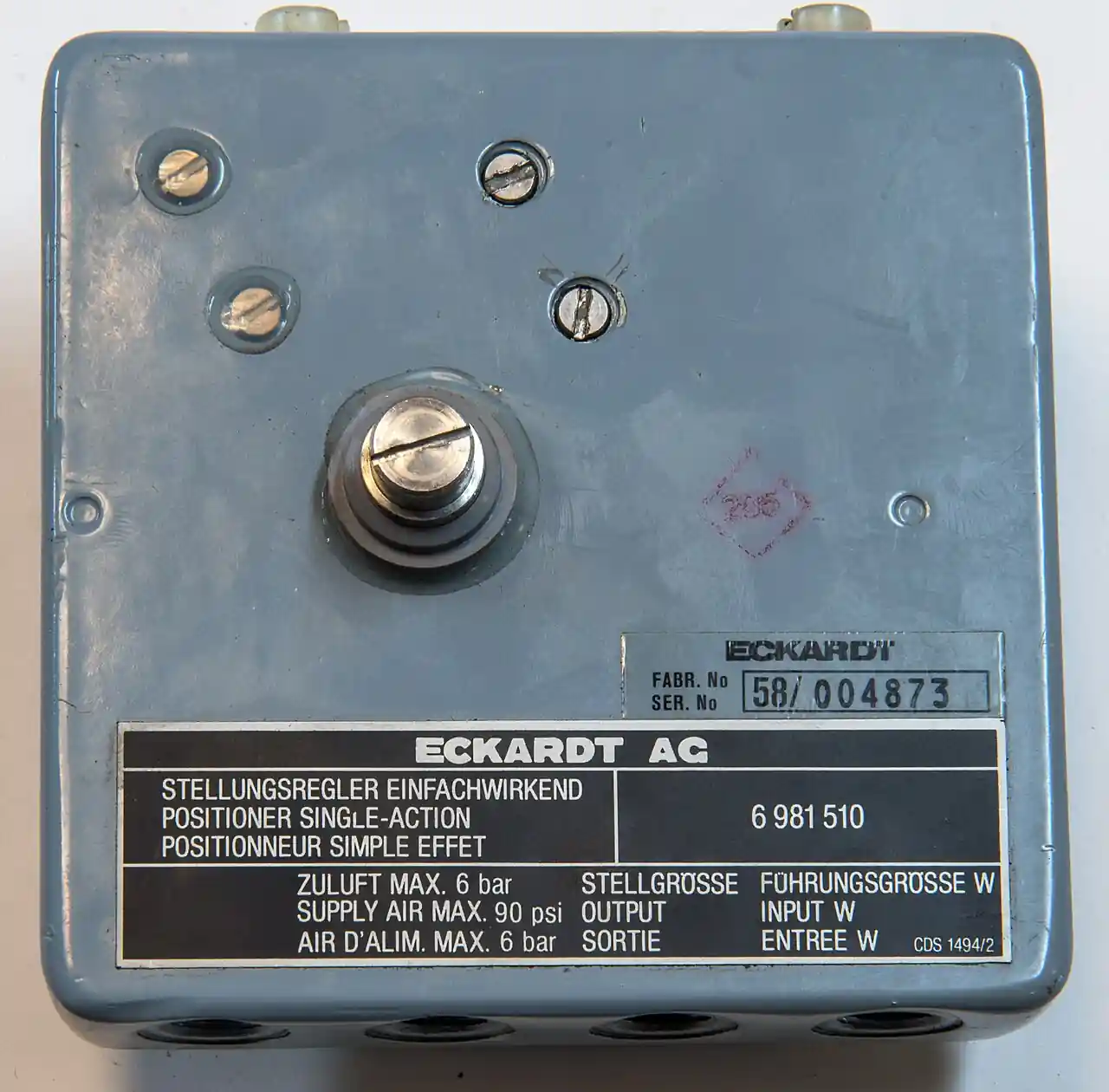
An I/P converter, an electro-pneumatic transducer, is the signal bridge of the process plant: it accepts a 4 to 20 milliampere current from a controller, PLC analog output, or control system and produces a proportional pneumatic pressure, the classical 0.2 to 1 bar, 3 to 15 psi, instrument signal, that drives diaphragm actuators, pneumatic valve actuator cylinders, damper and louvre operators, relays, and other air-driven final elements. It is an open-loop device: the converter faithfully maps current to pressure, and what the actuator does with that pressure is the actuator's business, which is precisely the line that separates it from a valve positioner, the closed-loop instrument that measures stem position and corrects the air signal until the valve actually sits where commanded. Thousands of waterworks, utilities, and process retrofit loops buy the converter every year precisely because their actuator or relay needs a clean proportional air signal and does not need, or does not budget for, closed-loop position control.
Specifying one is four linked decisions: the output span and its action, direct or reverse, plus any split-range calibration when one controller drives two valves in sequence; the pneumatic capacity, because a converter feeding a large diaphragm case fills it at a finite flow rate and a volume booster or pilot capacity option decides stroking speed; the environment, vibration at the yoke, ambient temperature, and hazardous-area classification, which pick the housing, the mounting, and the explosion-proof or intrinsically safe variant; and the air supply quality, filtered and dry to the maker's particle and dew point spec, because the flapper-nozzle and relay internals are the finest clearances in the instrument air system. This page works each decision with catalog numbers and closes with the RFQ lines that make converter quotes comparable at engineering level.
This page treats the I/P converter as an instrument-grade signal device: force motor and flapper nozzle physics, output spans and split ranges, capacity and stroking-speed arithmetic, vibration and hazardous-area limits, the open-loop boundary against the positioner, and the RFQ lines that carry the whole specification.
Chapter 1 / 06
What an I/P Converter Is and What Is Being Decided
The device sits between two worlds. On one side is the electronic control chain: a 4 to 20 mA loop, sometimes with HART superimposed, sourced by a PLC analog output card, a single-loop controller, or the SCADA layer, a loop that carries one current value proportional to the command. On the other side is the pneumatic actuation world: diaphragm cases and cylinders that convert supply air at 1.4 to 7 bar into force and travel, the world of the control valve actuator, the damper operator, and the pneumatic relay. The converter is the entire interface: milliamperes in, a proportional branch pressure out, with the standard span 0.2 to 1 bar mapping the live 4 to 20 mA range, and variants covering 3 to 15 psi as the same physical span in imperial units, 0.4 to 2.1 bar for higher-force duty, and split calibrations that map partial current ranges onto full output spans.
What is being decided is whether an open-loop bridge is the right instrument at all, and then its hardware. The loop-architecture question first: if the final element is a modulating control valve whose position must follow the command against friction and varying load, the correct instrument is a valve positioner, which contains its own I/P stage and adds stem feedback; the standalone converter is the right instrument when the load is benign or the element is not a valve at all, a long-stroke cylinder, an air-to-open relay train, a damper with its own linkage physics, or when budget and simplicity dominate in waterworks-style loops. Then the hardware decisions: output span and action, direct, rising current gives rising pressure, or reverse, and the split-range points when two converters share one controller; capacity, the internal relay's flow rate against the actuator volume, with a booster relay when the arithmetic fails; environment, vibration, temperature, and area classification; and supply conditioning, the filter regulator and dryer that keep the nozzle clean.
The competitive frame keeps the selection honest. Against the valve positioner, the converter wins on price, roughly a third to a fifth, on air consumption, and on simplicity, and loses on everything that feedback buys: repeatability under stem friction, response independent of supply fluctuation, diagnostics, and characterized travel; the positioner is the correct instrument for real throttling valves, and its page treats that machine. Against a smart positioner with fieldbus, the converter is the legacy-economic choice, bought by the thousand in retrofits where the control system speaks 4 to 20 mA and the actuator is trusted. Against the electric actuator with its own 4 to 20 mA input, the pneumatic chain with a converter wins on speed and force density and fails-safe with springs; the electric actuator wins where instrument air does not exist. Against a VFD speed command, there is no contest because the quantities differ: the drive converts the same current into motor speed, a pump-side control move that often removes the valve entirely; the soft starter belongs even further away, in motor starting duty. The converter's niche is real and durable: proportional air, honestly made, at loop speed, from a two-wire command. The integration context is standard instrument practice: the converter sits on the same loop drawings as the pressure transmitter, its branch pressure read at the same HMI panel that displays the loop, and where plants migrate to digital networks the fieldbus gateway and IO-Link infrastructure absorb the same signals natively, which is the path most retrofit fleets eventually ride.
One positioning note: this page is the single-product page for the standalone converter. The valve positioner, the pneumatic valve actuator, and the control valve families each have their own pages; here the assumption is an open-loop current-to-pressure duty, and every number that follows is chosen for that world.
Chapter 2 / 06
How the Converter Turns Milliamperes into Pressure
The heart is a force motor, a balanced electromagnetic arrangement in which the loop current flows in a coil suspended in a permanent magnet's field, producing a torque or force proportional to current. In the classic flapper-nozzle architecture, that force acts on a flapper, a thin lever, positioning it against a nozzle that bleeds supply air to atmosphere; the nozzle's backpressure rises as the flapper closes the gap, so current becomes a few kilopascals of pilot pressure with sub-milliampere resolution. A pneumatic relay, a diaphragm or piston valve, then amplifies the pilot into the branch signal at usable flow, isolating the delicate torque motor from the actuator volume and holding the output stable against supply and load changes. The whole chain is continuous analog physics: no stepper, no digital loop inside the basic unit, which is why a well-made converter holds its calibration for years and why its failure modes are mechanical and pneumatic, not firmware.
The arithmetic of span and range defines the calibration. A direct-action unit maps 4 mA to 0.2 bar and 20 mA to 1.0 bar in the standard span, a 50-milliampere-to-bar slope in the loop's terms, and every intermediate current lands proportionally: 12 mA gives 0.6 bar, the midstroke pressure of a spring-diaphragm actuator. Reverse action inverts the map, 4 mA to 1.0 bar, for fail-closed actuator arrangements wired against the controller's failure mode. Split ranging divides the loop: a first converter calibrated 4 to 12 mA onto full output drives the small valve, a second calibrated 12 to 20 mA drives the large valve, and one controller commands two trims in sequence, the classical boiler and turbine bypass arrangement; the calibration is a bench exercise with a current source and a test gauge, and the RFQ states the points so the vendor delivers it set rather than "field-adjustable" and unset. High-output variants extend the ceiling: units mapping the loop onto 0 to 2.1 bar or, in the piston-cylinder world, onto the several-bar spans that a piston actuator's bias and span require, the Fisher i2P-100 class of instrument with output to roughly 4 bar for cylinder service.
Calibration
Input range
Output span
Duty
Direct standard
4 to 20 mA
0.2 to 1.0 bar, 3 to 15 psi
Default spring-diaphragm actuation
Reverse standard
4 to 20 mA
1.0 to 0.2 bar
Fail-closed wiring arrangements
Split range first valve
4 to 12 mA
0.2 to 1.0 bar
Sequential two-valve trim
Split range second valve
12 to 20 mA
0.2 to 1.0 bar
Large trim staging
High output, cylinder
4 to 20 mA
0 to 2.1 or to about 4 bar
Piston actuator bias and span
Static performance is a small table of numbers that the datasheet must state together: accuracy, typically within 1 percent of span, better units within 0.5; hysteresis and dead band, each below 0.5 percent of span for quality instruments; repeatability below 0.5 percent; and supply sensitivity, the output shift per bar of supply change, typically quoted below 0.1 percent of span per bar. The dynamic performance is the capacity story: the internal relay passes a finite flow, commonly of the order of 1 to 4 cubic meters per hour at nominal supply, and against an actuator volume the branch pressure slews at a rate set by that flow. A sizeable diaphragm case holding several liters needs the full relay flow for a second or more of travel; a long-stroke cylinder of tens of liters starves it, and the answer is a volume booster relay mounted at the actuator, a 1-to-1 repeater with high flow that keeps the converter's precision while removing the speed limit, or a converter ordered with a high-capacity pilot stage from the start.
Air consumption and supply quality close the physics. A steady-state converter bleeds continuously through the nozzle, typical quoted consumption around 0.3 to 0.6 cubic meters per hour of free air at nominal conditions, plus whatever the actuation draws; the plant air budget sums these across the fleet, which is why low-consumption designs sell. The supply wants to be clean and dry: filtered to the maker's particle spec, commonly 20 to 40 micrometers with a coalescing stage preferred, and dried to a dew point below the coldest ambient, because the nozzle and relay clearances are the finest in the air system and a frozen or oil-wet nozzle is the classic winter failure. The gauge and regulator at the converter, set to the maker's nominal 1.4 bar minimum and commonly 2 to 4 bar, are part of the instrument, not an accessory afterthought; supply pressure also bounds the achievable output, since the relay cannot deliver branch pressure at or above the supply, so high-span calibrations need the higher supply settings.
Chapter 3 / 06
Types, Construction, and Duty Boundaries
Types divide by output capacity and by intelligence. The basic panel or pipe-mounted converter is the signal workhorse: one current input, one pressure output, bench-set calibration, in a housing for clean environments. The yoke or actuator-mounted unit adds vibration tolerance and direct tubing to the actuator, the standard retrofit form on spring-diaphragm valves; quality units in this class carry vibration specifications to several g across a stated frequency band, because a torque motor on a cycling valve yoke lives in the worst vibration neighborhood in the plant. The high-capacity or pilot-relay versions integrate a larger relay stage for mid-size actuators. The booster-equipped configuration pairs the converter with a 1-to-1 volume booster at the actuator for large volumes and long signal runs. The intelligent converter wraps the same conversion in electronics with HART or digital configuration, alarm outputs, and self-diagnostics, effectively a positioner without the feedback linkage; it sells where the loop wants diagnostics but the final element is not a stem to measure. The explosion-proof and intrinsically safe variants carry the Ex certificates for classified areas, with the loop barrier or housing rules their certification implies.
Construction follows the two-worlds reality. The electrical side is a terminal block or a connector, loop-powered in the basic designs, consuming a voltage drop of a few volts within the loop budget; terminals and housings carry IP ratings, commonly IP54 in general purpose and IP65 or IP66 in the Ex and outdoor classes. The pneumatic side is a supply port, commonly 1/4 NPT, with the output port beside it and a gauge port to read the branch; internals are the torque motor, the nozzle and flapper assembly, the zero and span adjustment springs accessible under a cover, and the relay. Materials are aluminum housings with corrosion coatings or stainless for offshore and chemical duty, nitrile and fluorocarbon elastomers in the pneumatic path, and a sintered or mesh air intake filter on some models that must be in the maintenance schedule. Ambient windows run typically minus 20 to plus 70 deg C in general service, extended to minus 40 and to plus 80 in extreme variants, with the loop electronics and the Ex temperature class governing the exact lines.
Type
Typical envelope
Duty where it wins
Hard boundary
Panel or pipe mounted, basic
0.2 to 1.0 bar, about 1 Nm3/h capacity
Signal conversion in cabinets and skids
No vibration tolerance claim
Yoke mounted, vibration rated
to several g per maker curve
Direct on actuator, retrofit loops
Capacity still limited
High-capacity relay version
several Nm3/h flow
Mid-size diaphragm actuation
Price and air consumption
Converter plus volume booster
booster flow tens of Nm3/h
Large cases and cylinders, speed
Booster is a second device to mount
Intelligent, HART configurable
with alarms and diagnostics
Loops wanting supervision, no stem
Cost; overlaps positioner territory
Ex certified, flameproof or I.S.
ATEX or IECEx marking
Classified process areas
Certification governs wiring
Duty boundaries, sentence by sentence. Open-loop modulating valve with benign load and modest performance targets: the converter serves honestly, and thousands of waterworks loops run exactly this arrangement on butterfly and globe valves. Real throttling duty with friction, high differential, or characterized requirements: the valve positioner owns it, and the converter is the wrong economy. Large actuator volume with speed demand: converter plus booster, or the high-capacity version, or by architecture a positioner with its own high-flow stage. Damper and louvre operators, long-stroke cylinders, pneumatic relays: converter territory, because there is no stem feedback to buy. Retrofits on 4 to 20 mA loops with trusted actuators: the converter's commercial heartland, bought in lots against a one-line specification. Hazardous areas: the Ex variants carry the duty, with the certification file, not the housing color, as the evidence. High-vibration yokes without a vibration rating on the datasheet: remote-mount the converter on a wall bracket with tubing to the actuator, because a torque motor is a precision balance and an unbalanced one is a service call generator. Where the plant question is motor speed rather than valve position, the VFD consumes the same 4 to 20 mA for a different purpose, and the converter is not in that conversation.
Chapter 4 / 06
Key Specification Parameters
The decode table is the datasheet skeleton. Every row is an RFQ line, and the two right columns are what each row decides and what it costs to leave blank.
Parameter
Typical catalog spread
What it decides
Input signal and action
4 to 20 mA, direct or reverse, others by order
Loop wiring and fail behavior of the signal chain
Output span and calibration
0.2 to 1.0 bar standard, 3 to 15 psi, split ranges, to about 4 bar
Actuator match and sequencing across two valves
Supply pressure range
1.4 to 7 bar typical, nominal 1.4 to 4
Headroom for the output ceiling
Flow capacity
about 1 to 4 Nm3/h by relay
Stroking speed against actuator volume
Accuracy, hysteresis, repeatability
0.5 to 1 percent span each class
Loop performance the open loop can claim
Supply sensitivity
below about 0.1 percent span per bar
Output honesty under air header swings
Vibration rating
to several g in stated band, or none
Whether yoke mounting is legitimate
Ambient and storage window
minus 20 to plus 70 deg C typical
Outdoor and winter survival
Housing, IP, and Ex
IP54 to IP66, ATEX or IECEx options
Environment and area classification fit
Ports and mounting
1/4 NPT supply and output, panel, pipe, yoke
Installation scope and gauge provision
The capacity row is the one that separates a working loop from a slow one. State the actuator volume and the required full-stroke time, and require the maker's flow at nominal supply: a converter passing 1 cubic meter per hour into a 5-liter diaphragm case completes a full reversal in a comfortable second or two, while the same converter into a 40-liter cylinder is a stroking-time problem wearing a calibration certificate. The remedies ladder in cost: high-capacity relay version, converter plus 1-to-1 volume booster at the actuator, or a different architecture. What is not a remedy is raising supply pressure, which raises the ceiling without raising the flow and quietly buys the next failure.
The calibration row is the one that decides commissioning day. Write the five points, output at 4, 8, 12, 16, and 20 milliamperes, with tolerance against the required span, and require delivery bench-calibrated with a certificate: split-range installations in particular arrive either set or as an afternoon of bench work the schedule did not contain. The action row belongs with the failure philosophy: direct or reverse action decides whether loop failure, current to the minimum, drives the branch to its minimum or maximum, and the actuator's spring combined with the wiring convention must land the process in its safe state; the combination is a hazard-review line, not a commissioning preference.
The vibration and environment rows decide the mounting. A vibration rating on the datasheet, in g across a stated band, licenses yoke mounting on a cycling actuator; its absence mandates wall or pipe mounting remote from the stem's shocks, with tubing run and supported. The IP rating and the Ex marking govern outdoors and classified areas respectively, and the Ex choice, flameproof housing or intrinsically safe loop, decides the wiring method and the barrier schedule before purchase, because retrofitting certification onto an installed fleet is not a thing. The ambient window pairs with the air dryer spec: a converter rated to minus 20 with wet supply air at minus 25 ambient is a January service call either way.
The accessory stack completes the specification: a gauge on the branch, a filter regulator at the unit set to nominal supply, an isolating manifold for zero checks, the volume booster where capacity demands it, and drip legs in the tubing where condensate can collect. Budget the stack with the instrument or discover it missing at loop check; the certificate stack, Ex file, calibration certificate, and material certificates by project class, closes the delivery ticket. A quote missing either stack is not cheaper, it is later.
Chapter 5 / 06
Selection Decision Factors and RFQ Language
The decision sequence runs from the loop architecture outward, because every later step prices the earlier one.
Decide the architecture first: if the final element is a throttling valve whose position must be guaranteed, specify a valve positioner; specify the converter when the element needs proportional air, not position feedback, or when open-loop performance is adequate and economy dominates.
Write the signal contract: input range and action, output span, and for split-duty the exact calibration points of each converter in the sequence, with the fail direction traced through loop failure to the actuator's spring.
Size the capacity: actuator volume and required stroke time against the maker's flow, with the booster decision made on arithmetic before the purchase order, not after the first slow-stroke complaint.
Match the environment: vibration class versus mounting plan, ambient window versus site extremes, IP and Ex against the area schedule, with the wiring method fixed by the Ex choice.
Condition the supply: filter regulator, particle and dew point spec against the coldest ambient, gauge provision, and the header pressure available versus the output ceiling the calibration needs.
Plan the integration: tubing route and supports, manifold for zero checks, spare fuses and loop budgeting in the PLC output card, and the five-point calibration record format commissioning will keep.
Close with the commercial lines: bench-calibrated delivery with certificate, spares and service kit pricing, warranty terms against the calibration stability claim, and lot pricing for fleet retrofits.
The cost comparison is honest because the converter's whole identity is economic. Against a smart positioner at several times the price, the converter plus booster still prices far below and consumes less air, and for waterworks-style open-loop loops on butterfly valves the saving across a hundred loops is a budget line of its own. Against doing nothing, in a pneumatic-only plant held back from DCS integration, a hundred converters plus tubing is the entire modernization cost, which is why the device sells by the lot in utility retrofits. The dishonest comparison is converter versus positioner on a real throttling valve: the saved money returns as loop performance, seat wear from hunting, and summer tuning visits, because open loop buys neither friction immunity nor diagnostics. Table the decision on cost per loop per year including the maintenance the architecture implies, and the boundary writes itself.
Duty
Configuration to specify
Watch line
Open-loop valve, benign load
Yoke or pipe mounted, standard span
capacity vs actuator volume
Split-range two-valve trim
Two units, 4 to 12 and 12 to 20 mA
bench calibration certificate
Large cylinder or damper
Converter plus 1-to-1 volume booster
booster at the actuator
High-span piston actuation
High output version to about 4 bar
supply headroom above ceiling
Classified area loop
Ex variant, I.S. or flameproof
wiring method fixed by certificate
Vibration-heavy yoke
Vibration-rated unit or remote mount
rating in g with band stated
The RFQ language that makes quotes comparable, written as the datasheet lines a vendor must answer with numbers: input range and action; output span with the five calibration points and tolerance; supply pressure minimum, nominal, and maximum with flow at nominal; accuracy, hysteresis, repeatability, and supply sensitivity as percent of span; air consumption at steady state; vibration rating with band or the statement that none is claimed; ambient window; housing IP and Ex certificate file; ports and mounting; delivered calibration certificate; and the accessory stack included. A quotation answering those lines is an instrument specification; anything else is a housing with a price.
Chapter 6 / 06
Installation, Standards, Failure Modes, and Maintenance
Installation follows the signal chain discipline. Wire the loop with the polarity and the loop budget observed, the converter's voltage drop inside the output card's capability, and the shield grounded at one end per the control system's practice. Pipe the supply through the filter regulator, set to nominal, with the branch gauge visible at the unit, and run tubing to the actuator short, sloped, and supported, stainless or copper per plant standard, with a drip leg where the run dips. Mount per the vibration decision: yoke-mounted only with a rating that covers the actuator's cycling shocks, otherwise on a wall bracket remote from the stem with the tubing accounted. On split-range pairs, label each unit with its calibration points on the tag, because two identical-looking converters with different spans are the commissioning industry's favorite riddle. Provide the loop test points, a current meter jack or the DCS faceplate, and the manifold for branch zero checks, and commissioning becomes an afternoon instead of an investigation.
The standards frame is the instrumentation world's own. Signal levels descend from the ANSI and IEC analog convention, 4 to 20 mA with the live zero, and the pneumatic 0.2 to 1 bar signal from its ISA lineage; the device's own conformity rides on the maker's performance statements to IEC 61298 style test practice and on the Ex certificates, ATEX directive or IECEx scheme, that govern classified-area installation. Loop documentation, calibration records, and the Ex wiring method answer plant ISA-101-class engineering practice rather than a single device standard, which is why the calibration certificate and the labeled split ranges are the acceptance evidence an auditor asks for first.
Failure modes arrive in a predictable order, and each has a specification answer. Nozzle contamination from wet or oily air shows as output drift and eventual stickiness at one calibration point: the answer is the filter regulator and dew point spec, the intake filter cleaned on schedule, and the annual five-point check catching drift before the loop does. Supply dropout shows as output collapse to the relay's floor with the loop current healthy: the answer is a header pressure alarm and the regulator set correctly, and the diagnosis is one gauge read with the loop commanded to midspan. Vibration-induced calibration shift shows as a span that walks between checks on yoke-mounted units: the answer is the vibration rating, remote mounting, or the next service cycle catching it. Zero and span spring drift with temperature extremes shows as seasonal offset: the answer is the ambient window honestly matched, and the winter check scheduled. Coil open circuit shows as output pinned at zero or maximum with no current: the answer is a spare unit in the stores mix, because the field fix for an open torque motor is replacement, five minutes with two wrenches and a calibration. Booster relay hunting on large volumes shows as actuator buzz: the answer is the booster's adjustment or a needle valve damping the branch, specified with the booster, not improvised.
Maintenance is a small calendar. Quarterly in the first year, then semiannually on stable units: the five-point calibration check against a certified gauge and loop calibrator, the intake filter inspected, the branch zero verified against the actuator's benchset. Annually: the regulator drain, the tubing drip legs blown, the mounting fasteners re-torqued on vibrating services, and the Ex housing seals inspected where the certificate requires. Keep one spare per fleet-fraction, one in twenty is a common policy, plus the gasket and filter kit. Log each check on the loop record with the as-found and as-left points, because the drift history is the calibration interval's evidence and the warranty conversation's substance. A converter that holds its five points for three years is the norm for quality units; one that does not was usually installed without its air conditioning stack.
The commissioning record closes the loop: loop current source and values, branch pressures at five points, supply pressure and gauge reading, actuator volume and observed stroking times both directions, mounting and tubing route, Ex wiring method where applicable, and the tag photo. One page per instrument, kept with the loop folder. Plants that keep it calibrate on evidence; plants that do not calibrate on folklore, and folklore is what the next retrofit replaces.
FAQ
What is the difference between an I/P converter and a valve positioner?
The converter is open loop: it maps 4 to 20 mA faithfully into 0.2 to 1.0 bar and stops there, with no knowledge of what the actuator did. A valve positioner is closed loop: it measures stem position and adjusts the air until the valve actually sits at the commanded point, adding friction immunity, repeatability, and diagnostics. Choose the converter for open-loop economics and non-valve loads; choose the positioner whenever valve position must be guaranteed.
Can one 4 to 20 mA loop drive two valves in sequence?
Yes, by split ranging: the first converter is calibrated 4 to 12 mA onto its full output span and the second 12 to 20 mA onto its span, so the small trim moves first and the large trim picks up beyond midloop. Order both units bench-calibrated with certificates and tag each with its points, because two identical housings with different calibrations are the classic commissioning mix-up.
Why is my actuator slow even though the converter output is correct?
Capacity, not calibration. The converter's internal relay passes a finite flow, commonly 1 to 4 cubic meters per hour, and a large diaphragm case or cylinder fills at a rate set by that flow. Fix it with a high-capacity relay version or a 1-to-1 volume booster mounted at the actuator; raising supply pressure raises the ceiling without raising the flow and only buys the next failure.
What supply air quality does the converter need?
Filtered and dry: particle filtration to the maker spec, commonly 20 to 40 micrometers with a coalescing stage preferred, and a dew point below the coldest ambient. The flapper-nozzle and relay clearances are the finest in the instrument air system, so wet or oily air is the classic drift and winter-freeze failure. The filter regulator at the unit is part of the instrument, not an accessory.
Can I mount the converter directly on the valve yoke?
Only if the datasheet carries a vibration rating covering the actuator's cycling shocks, typically stated in g across a frequency band; the torque motor is a precision balance and unbalanced it drifts. Without a rating, remote-mount on a wall or pipe bracket with tubing to the actuator. The vibration line belongs in the RFQ, because retrofitting a mounting decision is cheaper than retrofitting a calibration habit.
What output span do I need beyond the standard 0.2 to 1 bar?
Match the actuator. Spring-diaphragm actuators live on the standard 0.2 to 1.0 bar span. Piston and cylinder actuators need higher spans, and high-output converters map the loop onto roughly 0 to 2.1 or up to about 4 bar, with supply pressure held above the ceiling the calibration demands. State the required output at 4 and at 20 milliamperes and the supply available, and let the vendor's range table answer.
How often should an I/P converter be calibrated?
Quarterly in the first year, semiannually once the drift history proves stability, with a five-point check against certified instruments: output at 4, 8, 12, 16, and 20 milliamperes against a test gauge. Quality units hold their points for years when the air supply is clean and dry; the drift record on the loop folder is the evidence that sets the interval. The field check between calibrations is one gauge read at a commanded midspan.