An oil in water analyzer is an instrument that measures hydrocarbon oil concentration in water, online on a flowing stream or as an automated bench determination, at ppb through mg/L levels. Plant documents list it as an oil in water monitor, permits name it an oil content analyzer, and offshore data systems tag it a produced water analyzer, but the purchase is one specific thing: a defensible oil number on a stream whose oil content is a discharge limit, a permit condition, or an early leak signal. Two methods carry nearly all of the duty, ultraviolet fluorescence for fast online monitoring and infrared solvent extraction for compliance grade totals, and they answer subtly different questions about the same water. Choosing between them, and proving the plumbing that feeds them, is what this page is about.
Procurement engineers meet these analyzers on offshore platforms against produced water discharge limits, in refinery and terminal effluent stations against permit concentrations, in power plants watching cooling water for lube oil and fuel leaks, and on vessels where bilge discharge must alarm at 15 ppm. The decision this page settles is narrow and practical: which fraction is regulated or sought, dispersed droplets or dissolved organics or total extractable oil; which method reads that fraction honestly; whether the installation is an in-line probe, a side-stream fast loop, or a cabinet monitor; and how the online number is anchored to the laboratory method the permit names. The answer lands as an RFQ line set: matrix and oil type, range, method, sample conditions, installation, calibration basis, and the standards the measurement traces to.
This page treats the oil in water analyzer as a purchasing object: the fluorescence physics and the extraction chemistry behind the number, the ranges and response times of the shipping families, the sample plumbing that decides whether the number means anything, and how all of it is written into an RFQ. It is written for engineers who issue purchase specifications, not for readers who want a brochure summary.
Chapter 1 / 06
What an Oil in Water Analyzer Is and What Is Being Decided
An oil in water analyzer is an optical or wet chemistry instrument whose input is a water stream carrying hydrocarbons in three physical forms: dispersed droplets, dissolved and emulsified fractions, and occasionally free oil riding the surface. What the instrument actually reports depends entirely on its method. An ultraviolet fluorescence unit reads the aromatic hydrocarbons inside the droplets and the dissolved phase, in ppb to ppm; an infrared extraction unit acidifies a measured sample, transfers the oil into a solvent, and counts carbon hydrogen bonds in mg/L; a scattering instrument merely watches droplet haze and hopes it is oil. The first purchase decision is therefore not a brand but a fraction: the RFQ must state whether the regulated or sought quantity is dispersed oil, dissolved organics, or total extractable oil, because the method follows from the fraction and not the reverse.
The measurement earns its budget from three duty classes. Offshore produced water discharge is governed in the northeast Atlantic by the OSPAR performance standard context of 30 mg/L dispersed oil, monitored as a monthly average compliance number on the overboard line, with permits elsewhere quoting similar mg/L limits; refinery and terminal effluent permits carry mg/L oil limits of their own. Marine bilge water must pass treatment with alarm capability at 15 ppm before overboard discharge under MARPOL Annex I context, which makes the bilge alarm its own approved instrument class. And in power plants and industrial cooling circuits, an oil in water monitor on the cooling water watches for the lube oil or fuel side of a condenser or exchanger leak, where the value is early warning at ppb rather than compliance at mg/L. Continuous online duty serves all three: compliance averaging needs it, upset capture needs it, and a grab sample campaign cannot see a two hour excursion at 3 a.m.
What is being decided in this purchase is five commitments at once. First, the fraction commitment: dispersed, dissolved, or total, written in the same words the permit uses. Second, the method commitment: fluorescence for speed and sensitivity, extraction for compliance grade totals, or both in layers. Third, the installation commitment: an in-line probe in the main, a side-stream fast loop through a sample conditioning system, or a cabinet sequencing several points, each with different sampling bias. Fourth, the calibration commitment: the instrument is calibrated against an oil, and the field oil must be that oil, or a documented correlation must bridge the difference. Fifth, the sample integrity commitment: oil in water is non-uniform by physics, so tap placement and droplet preserving plumbing decide more of the accuracy budget than the sensor does. A quotation that answers only the range line is a box price, not a measurement.
The instrument lives among the water monitoring siblings, and this page does not replace them. The generic panel family is covered by the online water analyzer umbrella page, pH and conductivity and turbidity instruments that share cabinets and shelters with the oil channel without overlapping it: a pH meter and a conductivity meter ride every effluent train, a residual chlorine analyzer sits where disinfection is permitted, an ORP meter watches oxidation control, a dissolved oxygen meter belongs to the aeration basin, a phosphate analyzer covers nutrient limits, and a turbidity meter watches solids; none of them sees oil. A TOC analyzer measures total organics, a much wider bucket that includes humics and solvents alongside hydrocarbons, so an oil event hides inside a TOC reading rather than standing out of it. A gas analyzer covers the volatile hydrocarbon fraction in the vapor phase, offgas and headspace duty the water phase measurement misses by construction. In the laboratory, the bench spectrophotometer carries the colorimetric methods that share the effluent bench, while the extraction gravimetry and chromatography referees live in the wet lab. Downstream of the measurement, a coalescing filter, API separators, and hydrocyclones treat the water; they do not measure it, and buying treatment without measurement is how permit excursions stay invisible until a regulator finds them. On high concentration streams and interface control duty, a densitometer does density accounting, a different physics for a different regime. The boundaries are stable, and the selection chapter argues them fully.
Compressed to one sentence, the decision is whether a defensible oil in water number is bought as a system, fraction and method matched to the permit, installation matched to the hydraulics, calibration matched to the field oil, and plumbing matched to the physics of droplets, or as a probe part number threaded into the nearest nozzle. The chapters that follow supply the physics, the hardware families, the datasheet rows, the selection logic, and the failure modes needed to write it the first way.
Chapter 2 / 06
How Oil in Water Sensing Works
The fluorescence method exploits one molecular fact: polycyclic aromatic hydrocarbons, the PAH fraction of crude and refined oils, absorb ultraviolet light and re-emit part of it at longer wavelengths. The analyzer excites the flowing sample in the ultraviolet, commonly near 254 nm on mercury lamp and xenon flash instruments, collects the emission through optical filters above the excitation band, and converts photodetector current to an oil concentration through a calibration curve. The intensity is proportional to aromatic content present in the measurement volume, which is the method's strength and its trap at once: sensitivity reaches ppb, response is effectively instant, and nothing is consumed, but a light condensate and a heavy crude with the same mass concentration can differ severalfold in fluorescence, so the calibration must be built on the site's actual oil or correlated to it. Laser induced fluorescence instruments push the same physics to tighter detection with a laser source, and fiber optic probes carry the excitation and emission to an in-line optical window, which is how most subsea and pipeline deployments are built.
The infrared extraction method is older, heavier, and still the compliance backbone in many permits. A measured sample is acidified, the oil is extracted into a solvent, and the extract is read in an infrared photometer at the carbon hydrogen stretch near 3.4 to 3.5 micron, where absorbance scales with the mass of oil transferred. The Horiba OCMA-500 class oil content monitor is the reference execution, automating the extraction and measurement in one bench cabinet; laboratory versions run the same chemistry by hand with larger volumes. The solvent is part of the method's history: the original formulations used Freon-113, banned under the Montreal Protocol, and the shipping replacement family, S-316 on the Horiba instruments and equivalent halogenated solvents elsewhere, carries its own purchase and disposal logistics that belong in the cost of ownership. Extraction reads the total oil it can transfer, aromatics and saturates alike, which is why it anchors permits while fluorescence anchors process control.
What the two methods report deserves precise language, because permits are precise about it. Dispersed oil is droplets suspended in the water phase, the fraction an OSPAR style produced water limit regulates, and both methods see it if the sample reaches them intact. Dissolved organics are hydrocarbons and related molecules in true solution; fluorescence sees the aromatic part, extraction sees most of the transferable part, and the difference matters when a permit is written as total petroleum hydrocarbons, TPH, the umbrella the laboratory methods define after extraction. State the basis on every document: an online fluorescence reading reported as diesel equivalent, a laboratory extraction reported as crude, and a gravimetric result reported as n-hexane extractable material are three different numbers on the same water, and only the stated basis makes them comparable. The cheap surrogate, a scattering or haze reading off a turbidity meter platform, responds to any droplet or particle and cannot distinguish oil from silt or air; it is a tripwire, not a measurement, and should be specified as such or not at all.
The family numbers, stated as ranges rather than promises: online fluorescence spans run about 0 to 1000 ppb on the low range with ppm class spans above it; extraction based instruments cover roughly 0 to 200 mg/L family; accuracy of 5 to 10 percent against the calibration oil is the honest expectation on both; response runs seconds on an online fluorescence flow cell and minutes per determination on an automated extraction cycle. Detection at the bottom of a fluorescence span is real but calibration bound, and the qualifier against the calibration oil belongs next to every quoted figure. Two niche families complete the landscape: photoacoustic instruments, which listen for the pressure pulse of absorbed light and hold calibration better on dark oils, and fiber optic surface sensing probes, which read the oil wetting a window; both are special order answers to special problems, not general purchase defaults.
The sampling truth closes the physics chapter, because it defeats more installations than any sensor limitation. Oil in water is non-uniform by nature: free oil floats, droplet size swings with turbulence and chemistry, and concentration stratifies in horizontal runs and quiet zones. A tap in a quiet zone reads a bias no analyzer corrects downstream; a long horizontal sample line lets droplets rise out of the sampled core; anything that coalesces droplets ahead of the reading point, including a coalescing filter or a tortuous flow path, removes exactly the fraction being measured. The discipline is isokinetic extraction from a mixed zone through a vertical riser, short runs, steady velocity, and a bubble trap ahead of any optical cell. Half the accuracy budget of a working installation is spent in the pipe before the first photon or solvent molecule is involved, and chapter 6 returns to this in installation terms.
Chapter 3 / 06
Methods, Construction, and Duty Boundaries
The in-line fluorescence probe is the minimal installation: an optical head with an excitation source, a window, and a detector, threaded or flanged directly into the main line, reading the water that passes its face. Its virtues are structural, no sample line to stratify or foul, no shelter, no fast loop pump, and seconds class response to an upset. Its limits are equally structural: it reads only the oil that crosses its optical path, so a stratified line biases it; the window fouls in the stream and needs a wiper or air blast cleaning arrangement; and service means a line entry or a retractable fitting with its own isolation hardware. On a well mixed produced water line downstream of final separation, the in-line probe is the honest offshore default; on a stratified or slow line it is a random number generator with a calibration certificate.
The side-stream fast loop is the installation most cabinets want. Flow is drawn from a mixed zone, let down from line pressure, typically 1 to 5 bar reductions toward ambient class, through a sample conditioning system that delivers a steady 0.5 to 2 L/min at the flow cell, with a bubble trap and a strainer protecting the optics; a solenoid valve on each incoming line lets one cabinet sequence several sample points on a programmed roster. The fast loop keeps transport delay short and gives the analyzer a controlled velocity across the window, but its plumbing is now part of the measurement: every elbow, horizontal run, and dead leg between the tap and the cell is a place droplets can rise, coalesce, or collect, and the installation standard in chapter 6 exists for that reason. Cabinet monitors built this way, the Advanced Sensors by PAC family among them, carry the flow cell, optics, cleaning, and electronics in one hazardous-area-rated enclosure for offshore and refinery duty.
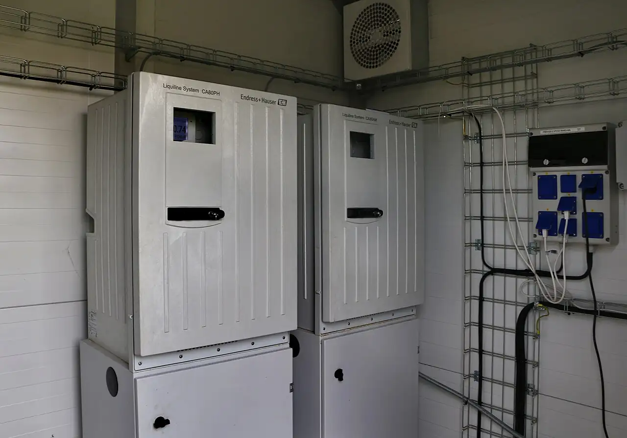
The extraction monitor is the third construction: a bench or wall cabinet that meters a sample volume, acidifies it, extracts with S-316 or the regional equivalent, reads the infrared absorbance, and reports mg/L per determination, the Horiba OCMA-500 class being the long-standing reference, with automated versions cycling every few minutes. It is slower than fluorescence and consumes solvent, but it reads total extractable oil in the language many permits are written in, which is why plants run it as the compliance instrument beside a fluorescence unit used for control. On offshore decks and in refineries, the whole question of hazardous areas arrives with any of these constructions, and ATEX and IECEx certified executions, with intrinsically safe field wiring and appropriate enclosures, are standard catalogue items rather than specials; a purchase that discovers area classification after delivery is a purchase that returns itself.
The comparison table compresses the methods into the form a specification meeting argues from; values are the common spans of the established families and must be confirmed against the model datasheet before order.
Method family
Construction and response
Range class
Duty it wins
UV fluorescence, in-line probe
Optical head in the main, window cleaning, seconds response
ppb to ppm spans
Upset capture on well mixed lines
UV fluorescence, side-stream cabinet
Fast loop, flow cell 0.5 to 2 L/min, multi-point sequencing
Acidify, S-316 extraction, IR photometry, minutes per cycle
0 to 200 mg/L family
Compliance totals in permit language
Scattering and haze surrogate
Optical turbidity platform, no oil specificity
Relative units
Tripwire only, not a measurement
Duty boundaries keep the families honest against each other. Fluorescence wins speed and sensitivity and loses calibration universality. Extraction wins permit language and total oil and loses speed and solvent innocence. The surrogate wins cost and loses everything else. In mature plants the answer is layered: fluorescence online for control and alarms, extraction on a schedule for the compliance number, and the laboratory referees in chapter 6 behind both. No member of the family measures the volatile fraction, which is gas phase duty, and none of them treats the water, which is separation and filtration duty downstream of the sample tap.
Chapter 4 / 06
Key Specification Parameters
The datasheet rows below decide whether a quoted analyzer matches the duty; values are stated as the common industrial spans of the established families and must be confirmed against the model datasheet before order.
Attribute
Typical range or options
What it decides
Method
UV fluorescence, laser induced, IR extraction, surrogate
Fraction read, speed, and compliance language
Range
0 to 1000 ppb class fluorescence low span; 0 to 200 mg/L extraction
Coverage from leak watch to permit compliance
Accuracy
5 to 10 percent against the calibration oil
Margin against the limit, basis stated or worthless
Response time
Seconds on fluorescence; minutes per extraction cycle
Upset capture versus compliance averaging
Calibration basis
Site oil, named standard, or correlated factor
Whether the number is defensible to a regulator
Sample flow
0.5 to 2 L/min at the flow cell, steady
Fast loop and conditioning sizing
Sample pressure letdown
1 to 5 bar reduction toward ambient class
Regulator stage count and wet end rating
Cleaning and validation
Wiper, air blast, ultrasonic clean, check standard
Uptime of the optical path between services
Area rating
General purpose, ATEX, IECEx by zone
Legal installation on offshore and refinery decks
Outputs and protocol
4 to 20 mA, Modbus, alarm relays
DCS integration and discharge interlock routing
The calibration basis row deserves its own paragraph because it is where quotations go vague. An online fluorescence instrument is calibrated at the factory against some oil, often a diesel or a standard dispersion, and its readings are reported in that equivalent unless the buyer says otherwise; a permit written in crude mass or in gravimetric extractable material is a different number on the same water. The specification must name the calibration oil, require the correlation factor against the site oil to be established at commissioning, and require paired laboratory checks on a schedule. The accuracy figure inherits the same qualifier: 5 to 10 percent against the calibration oil is a family honest claim, and 5 percent against the wrong oil is a precise wrong number. Datasheets that quote accuracy without a basis are quoting laboratory peak performance, not field performance, and the RFQ should say so back to them.
The installation architecture rows decide what the instrument actually sees, and the table below states the three constructions with what each one costs the measurement.
Architecture
Sample handling
Bias and service profile
In-line probe in the main
None, line conditions at the window
Reads only its optical path; service needs line entry or retractable fitting
Side-stream fast loop
Letdown, steady 0.5 to 2 L/min, bubble trap, strainer
Controlled window conditions; plumbing must preserve droplets end to end
Cabinet monitor, multi-point
Sequenced streams by solenoid valve, shared cell
One instrument, several points; roster latency and carryover flush between points
Bench or automated extraction
Grab or autosampler volumes, solvent on site
Compliance grade totals; minutes per determination and solvent logistics
Integration rows close the specification. Each monitored stream carries a 4 to 20 mA output or a mapped Modbus register set, with high and high-high alarms routed to the DCS and, on overboard and bilge duty, interlocked to the discharge valve or stopping function so the analytical result has legal teeth. On hazardous area decks the loop passes through a safety barrier or an intrinsically safe isolation stage between the zoned enclosure and the safe area system, and that barrier belongs in the analyzer scope of supply rather than in a later electrical change order. The hydraulic context earns its own lines: a flow meter on the fast loop proves sample velocity at the cell, and an electromagnetic flowmeter on the effluent line itself turns the concentration into kilograms per day of discharged oil, the number environmental reports actually ask for. Diagnostic states, window dirty, no flow, lamp fail, calibration due, must page the same way the measurement does, and a solenoid valve roster fault is a data gap that a compliance report has to explain.
Chapter 5 / 06
Selection Decision Factors and RFQ Language
The selection sequence runs as a checklist, and each line eliminates a class of quotations before price comparison begins.
Write down the regulated or sought fraction in permit language: dispersed oil, dissolved organics, or total petroleum hydrocarbons, and let the method follow the fraction.
Fix the range and alarm setpoints: ppb leak watch bands on cooling water, ppm alarm bands on overboard lines, mg/L permit averaging on refinery effluent.
Fix the method against the duty: fluorescence online for speed and sensitivity, extraction for compliance totals, layered where both are needed.
State the calibration basis by name: the site oil, a named standard, or a correlation factor to be established at commissioning and rechecked on schedule.
Characterize the sample at the tap: pressure and temperature, available flow, distance to the cabinet, and the letdown and cooling hardware each tap needs.
Fix the architecture: in-line probe on well mixed mains, side-stream fast loop where optics need steady conditions, multi-point cabinet where one instrument serves several streams.
Fix the integration: outputs, protocol, alarm routing to the DCS, discharge interlock intent, and the safety barrier scope on hazardous area sites.
Add the logistics lines: solvent purchase and disposal for extraction units, check standards, window cleaning consumables, and the first year service kit.
Against the neighboring measurements the oil channel holds specific ground, and the comparison belongs here in the selection chapter rather than in a page title. The online water analyzer page is the umbrella over the generic panel family, and its instruments are the oil channel's cabinet mates rather than its competitors: a pH meter and a conductivity meter on every train, a residual chlorine analyzer where disinfection applies, an ORP meter on oxidation, a dissolved oxygen meter on aeration, a phosphate analyzer on nutrient limits, a turbidity meter on solids. The oil specific boundary runs against three of them. A TOC analyzer measures total organics, sees solvents and humics and hydrocarbons alike, and cannot isolate an oil event from a background shift; a turbidity meter responds to any droplet or particle and cannot tell oil from silt; a densitometer works the high concentration and interface regimes where density differences carry the information. A gas analyzer covers volatile hydrocarbons in the vapor phase, the fraction the water measurement structurally misses. In the laboratory the bench spectrophotometer carries the colorimetric effluent methods that share the bench, and the oil referees are gravimetry and chromatography. Around the measurement sit the treatment neighbors: a coalescing filter, hydrocyclones, and API separators polish the water after the tap, and a metering pump doses de-oiler chemistry into the separation train; treatment and measurement are bought together or the plant flies blind through its own process. Nothing on the list substitutes for the oil number, and the oil number substitutes for nothing on the list.
The application map below compresses the practice into the form a project file carries.
Application
Construction to specify
Check before order
Offshore produced water, OSPAR context
Side-stream fluorescence cabinet, ATEX or IECEx, extraction verification
30 mg/L averaging basis and monthly correlation to lab extraction
Refinery and terminal effluent permit
Multi-point cabinet on storm and process sewers, mg/L spans
Permit method named in the monitoring plan and matched by the instrument
Cooling water leak detection
In-line or side-stream fluorescence, low ppb span
Calibration oil matched to lube or fuel; alarm band above background
Bilge water 15 ppm alarm
Approved bilge alarm class instrument with stopping function
Type approval certificates from the flag or class society
Airport stormwater and deicing runoff
Transportable fluorescence plus extraction confirmation
Seasonal oil variability and calibration refresh cadence
Remediation groundwater
Low range fluorescence, laser induced on tight sites
Dissolved versus free product phases and turbidity interference
The RFQ block should be written once and reused: quantity and family; matrix and oil type, crude, condensate, diesel, lube, with the regulated fraction in permit words; expected range with alarm setpoints and the dissolved versus dispersed question answered; method with the reasoning stated so suppliers can challenge it honestly; sample conditions at each tap, temperature, pressure, flow, distance, and the conditioning hardware offered; installation architecture, in-line, side-stream, or cabinet, with the multi-point roster if any; calibration basis and the correlation procedure at commissioning; cleaning and validation routines with consumable intervals; hazardous area rating with the safety barrier scope; outputs, protocol, alarm routing, and any discharge interlock; and the verification method and frequency against the laboratory referees. A quotation returned without a named calibration basis, or with sample plumbing left as an exercise for the buyer, is incomplete at any price.
Chapter 6 / 06
Installation, Standards, Failure Modes, and Maintenance
Installation begins at the tap, not at the analyzer. The sample point goes into a mixed zone, an isokinetic tee in a vertical or well stirred run, never the bottom of a horizontal line where droplets have already risen out of the sampled core; from the tap the line runs short and vertical up to the sample conditioning system, which lets pressure down in controlled stages, holds 0.5 to 2 L/min steady at the cell, and passes the flow through a bubble trap and a strainer before the optics. Everything upstream of the reading point must preserve droplets: no coalescing filter, no tortuous needle valves, no long dead legs, because each one quietly removes the fraction being regulated. The coalescing filter and the separation train belong downstream of the tap, treating the water after the analyzer has seen it, and where de-oiler chemistry is dosed the metering pump takes its pace from the analyzer trend, tightening treatment when the overboard number rises. A solenoid valve at each inlet sequences a multi-point cabinet, and the valve seats and flush routines are part of the measurement, not merely of the plumbing. On decks and in zoned areas the whole wet train carries the area rating, and the signal passes a safety barrier on its way to the safe side.
Commissioning establishes the calibration the plant will live with. Calibrate the fluorescence unit against the site's actual oil where a dispersion can be made, or against the supplier standard with paired grabs to compute the correlation factor; step the instrument with a check standard at duty flow and record the true response; and run the first paired extraction or laboratory referee samples in the first week so the online number is anchored before anyone files it. Verify every alarm path, window dirty, no flow, lamp fail, by forcing it once, and verify the 4 to 20 mA scaling end to end into the DCS including the overboard or bilge interlock, which must be tested with the operations team standing at the valve. A commissioning record with the calibration basis, the correlation factor, the response time, and the forced alarm log turns the first audit into a formality.
The standards frame runs from regulator guidance through laboratory reference methods. Offshore northeast Atlantic produced water duty reads against the OSPAR produced water performance standards, the 30 mg/L dispersed oil context with its defined averaging and analysis expectations; marine bilge duty reads against MARPOL Annex I and the 15 ppm alarm with its type approval regime under the classification societies. The laboratory referees the online units are calibrated and verified against are EPA 1664A and 1664B, n-hexane extractable material and silica gel treated material by gravimetry, in United States permit practice, and ISO 9377-2, the solvent extraction and gas chromatography hydrocarbon oil index, in international practice; older permits still name infrared methods descended from the Freon era, which is the ancestry the S-316 solvent instruments carry. When the RFQ cites the permit, the referee method, and the instrument family together, the supplier knows the number is a chain from tap to courtroom, and prices the chain instead of the box.
Failure modes follow a short and predictable list. Window fouling is the daily one: oil films and solids coat the optical path and read as high or low depending on the geometry, and the answer is the cleaning arrangement, mechanical wipers, air blasts, ultrasonic baths, consumed on a schedule with the fouling rate logged at commissioning. Fluorescence drift shows as slow baseline movement between checks, absorbed by auto zero until it cannot be, and caught by the check standard cadence. Bubbles cross the cell as spikes, and the bubble trap plus a steady fast loop pump removes them; a pump sized for low flow lets droplets stratify in the run and quietly biases the sample toward the water phase. On extraction units the failure mode is logistics: solvent exhausted, expired, or impure, each of which produces confident wrong mg/L values, so solvent lot control belongs in the maintenance plan. Calibration mismatch is the quiet one: the online fluorescence and the laboratory extraction drift apart as the field oil changes with the process, and only the scheduled paired grabs catch it. And the solenoid valve roster fails as a seat leak, cross contaminating a clean stream with the previous point's oil, the classic false excursion on multi-point cabinets; a seat check at every service keeps the roster honest.
Maintenance is deliberately boring and budgeted in consumables. Weekly: alarm review, window fouling trend, fast loop flow check on the local flow meter. Monthly: check standard run and correlation log entry, cleaning element service where fitted, strainer and bubble trap inspection. Quarterly: full calibration refresh, paired laboratory grabs against the referee method, solenoid valve seat checks on multi-point rosters. Annually: optical service, solvent system overhaul on extraction units, electromagnetic flowmeter verification on the load arithmetic line, and a review of the calibration basis against the current field oil, because processes change and last year's correlation quietly expires. Spares held on site: one lamp or source module, one window or flow cell seal set, cleaning consumables, one solvent and reagent lot within shelf life for extraction units, and one check standard. The throughline of this page is that an oil in water monitor is a measurement chain whose weakest links are a window and a pipe fitting: kept clean, kept calibrated against the real oil, and kept droplet intact from tap to cell, it holds its stated class for years, and neglected on any of the three it produces numbers that look exactly as authoritative as good ones.
FAQ
Which method fits produced water discharge compliance?
Fluorescence and IR extraction answer different questions. Online UV fluorescence gives seconds class response at ppb to low ppm, ideal for process control and upset capture, but it responds to the aromatic fraction and must be correlated to the site's oil. IR extraction, automated in the OCMA class monitor or run in the laboratory, measures total extractable oil in mg/L and remains the compliance backbone many permits name. Many platforms run fluorescence online and verify by extraction.
What ranges and accuracy are realistic?
Online fluorescence spans about 0 to 1000 ppb on the low range with ppm class spans above it; extraction based instruments cover roughly 0 to 200 mg/L family. Accuracy of 5 to 10 percent against the calibration oil is the honest expectation on both, and the qualifier matters: the answer is only as good as the match between the calibration oil and the field oil. Response runs seconds on fluorescence and minutes per determination on extraction.
Why must calibration use the site's actual oil?
Because the two dominant methods see different parts of the oil. Fluorescence responds to polycyclic aromatic content, which varies widely between a light condensate and a heavy crude, so an analyzer calibrated on diesel can misread crude by a large factor. IR extraction counts carbon hydrogen bonds across the whole oil. State the calibration basis explicitly, as crude, as diesel, or as a site standard, and correlate the online fluorescence against extraction grabs on the real stream.
In-line probe or side-stream cabinet?
Each buys something. An in-line probe in the main needs no sample system and cannot stratify, but it reads only the oil that passes its optical path and service means a line entry. A side-stream fast loop through a sample conditioning system delivers steady flow at the cell, supports bubble traps and strainers, and lets one cabinet sequence several points with solenoid valve switching, at the cost of plumbing that must preserve droplets.
What does the 15 ppm bilge rule require?
MARPOL Annex I context requires bilge water treatment with alarm capability at 15 ppm oil before overboard discharge, and the bilge alarm is its own instrument class with type approval expectations. The measurement is dispersion sensitive, so the probe sits in a representative mixed flow, and alarm plus automatic stopping of discharge is the functional requirement. Certificates from the flag administration class societies belong in the purchase file, not as optional extras.
Why does sample plumbing decide whether the reading means anything?
Oil in water is notoriously non-uniform: free oil floats, droplet size swings with turbulence, and a tap in a quiet zone reads a bias that no analyzer can correct downstream. Take the sample isokinetically from a mixed zone, keep runs short and vertical up, and avoid anything that coalesces droplets ahead of the reading point, including a coalescing filter or a long horizontal run. Half the accuracy budget is spent in the pipe.
How are online readings verified against laboratory methods?
By paired samples on a schedule. The laboratory references are EPA 1664A and 1664B, n-hexane extractable material by gravimetry, and ISO 9377-2, the solvent extraction gas chromatography hydrocarbon oil index, with older infrared methods in some permits. Grab pairs taken at the analyzer tap, preserved and extracted promptly, establish the correlation factor the online fluorescence carries. Without that periodic pairing, an online number is a trend, not a measurement.