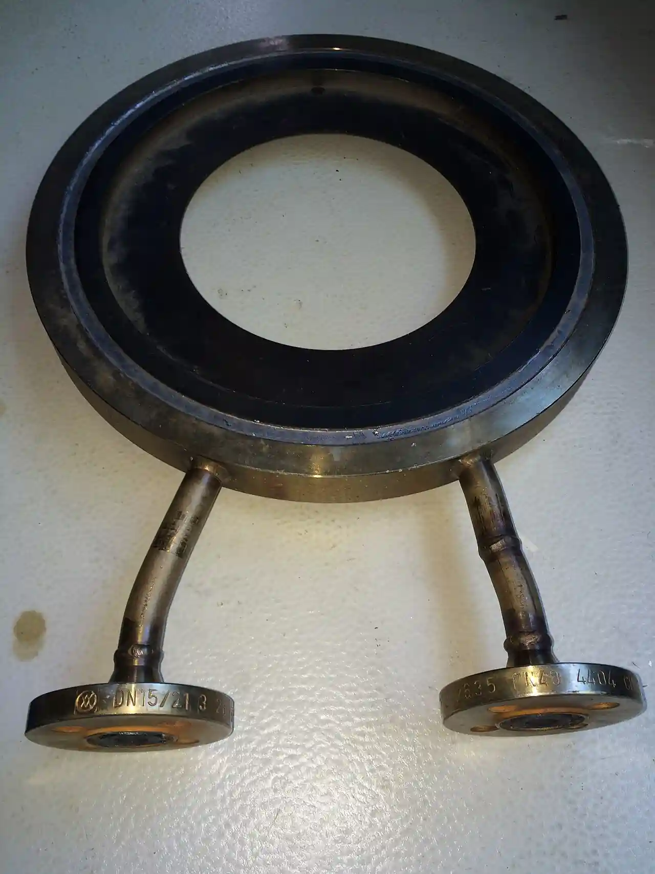
An orifice flange is a pressure retaining flange built to ASME B16.36 that works as one half of a matched pair, called an orifice flange union or OFU in maker catalogs, whose job is to clamp a thin orifice plate into the center of a pipe so the plate can act as the primary element of a differential pressure flow measurement. Beyond the ordinary flange body, the orifice flange carries three dedicated features: a pressure tap hole drilled through the rim on each side, positioned to open exactly 1 inch upstream and 1 inch downstream of the plate face; a set of jack screws that push the paired flanges apart so the plate can be exchanged without cutting the pipeline; and bore pins or machined recesses that center the plate on the pipe axis against the gasket faces. Unions are made in Class 150 to Class 2500 and DN 50 to DN 900 in common practice, in weld-neck, slip-on, and ring type joint styles.
Procurement engineers meet this hardware wherever liquid, steam, and gas flow is bought, sold, or balanced by head measurement: refinery charge lines, steam distribution, produced gas, process water, and fiscal metering skids. The flange pair is purchased as hardware, but it is one link in a chain. The plate generates the differential, the flange taps carry it out, impulse tubing and valves deliver it, a differential pressure transmitter converts it to a signal, and a flow computer applies the square root, density compensation, and totalization at the panel. The decision this page settles is narrow and practical: which class, facing, material, and tap drilling to order, how many jack screws the duty needs, what gasket and stud package holds the joint, and what installation practice keeps the meter run honest. The answer lands as an RFQ line set, and every chapter below feeds that line set.
This page treats the orifice flange as a purchasing object: what ASME B16.36 actually fixes on the hardware, how flange taps differ from corner, vena contracta, and pipe tap practice, how jack screws and bore pins turn plate exchange into a maintenance event instead of a pipe cut, and how class, facing, material, and gasket choices combine into a defensible RFQ. It is written for engineers who issue purchase specifications for meter runs, not for readers who want a flow measurement treatise.
Chapter 1 / 06
What an Orifice Flange Is and What Is Being Decided
An orifice flange looks like an ordinary pipe flange until you walk around it. A standard flange made to ASME B16.5 is a pressure retaining connector with a bolt circle, a gasket face, and a bore that matches the pipe. The orifice flange adds the infrastructure of measurement: the rim is drilled and tapped for pressure pickoff on each side of the clamped plate, lugs or bosses are machined for jack screws, and the face carries the recess and pins that register a plate of known bore exactly on the pipe axis. ASME B16.36 fixes the tap hole size and its location relative to the plate faces, the plate cavity, the jack screw provisions, and the tolerances that let a plate from one maker center correctly in a union from another. The flange is never the measuring element; the plate is. The union is the holder, the tap carrier, and the service access for that plate, and the accuracy of everything downstream depends on how well it clamps and where it taps.
What is actually being decided at purchase is a hardware set, and it is worth listing before any catalog is opened. First, the pressure class and facing: Class 150 to Class 2500, raised face for most duty, flat face for brittle or glass lined mating flanges, ring type joint for high pressure steam and gas. Second, the tap arrangement: this page's hardware carries flange taps in the rim, while corner taps, vena contracta taps, and pipe taps belong to carrier rings or the pipe wall, and the choice interacts with the union. Third, the material: A105 carbon steel as the default, LF2 for low temperature, F11 and F22 chrome alloy for hot service, F304 and F316 stainless for corrosive duty, with NACE MR0175 governing selections in sour service. Fourth, the service features: jack screw count, plate retention method, and the gasket and stud package that keeps the plate cavity sealed for years between openings.
The union also sits in the middle of a measurement chain, and the buyer who forgets the neighbors buys half a system. The full measurement is described in the orifice plate flowmeter page of this encyclopedia: plate, union, tap valves, impulse lines, and a differential pressure transmitter, with a flow computer at the panel when the signal must become custody mass or energy units. The same family of head type elements includes the venturi tube for low permanent pressure loss, the flow nozzle for high velocity steam, and the averaging pitot tube for large lines where a full bore element is uneconomic; a single point pitot tube serves velocity surveys rather than continuous duty. This page deliberately stays on the flange union itself, because that is the item quoted on the piping line list, and because the union is where installation error is made and later paid for.
One boundary deserves a sentence of its airtime before the details: the orifice flange union is a measurement element holder, not an isolation device. It clamps a plate with a hole through it, so it never blocks a line, and it is not a substitute for a line blind or a shutoff valve in any lockout scheme. Plants that ask it to double as isolation are asking a gasketed measurement joint to do a job its geometry cannot do, and the request should be corrected at the drawing stage rather than honored in the RFQ. Equally, the plate it holds is not a pressure relief device of any kind; protection belongs to hardware sized for that purpose elsewhere on the line.
Compressed to one sentence, the decision is whether the meter run hardware is bought as a set, class and facing and taps and jacking and gasket package stated together with the plate bore, or as two flanges pulled from a generic piping class with the measurement details left to whoever assembles them. The chapters that follow supply the mechanics, the tap geometry, the dimension logic, and the failure modes needed to specify it the first way, so that the RFQ describes hardware that will hold its calibration rather than hardware that merely bolts up.
Chapter 2 / 06
How the Orifice Flange Union Works
Mechanically the union is a pair of mirror image flanges bolted face to face with the plate between them. Each flange face carries a gasket, and the plate sits in the cavity between the two gaskets, registered by bore pins or a machined recess so its bore is concentric with the pipe bore within the tolerance the measurement can stand. Studs through the bolt circle clamp the sandwich; the pipe side of each flange is welded to the meter run pipe, weld-neck hubs on the common designs. Because the plate is a separate thin disk, it can be pulled, inspected, reversed, or replaced for a different bore, and that is the entire economic argument for the hardware: the expensive pressure boundary is permanent while the cheap measuring element is renewable.
The jack screws are what make the plate renewable. Each flange carries two to four jacked studs, depending on size, threaded into lugs on the rim and bearing against the opposing flange back. During a plate change the operator cracks the studs a few millimeters, runs the jack screws in to hold the gap open, wipes the old gasket if it is a slip style or breaks the joint wide on a spool arrangement, and slides the plate out along the pipe axis. The procedure is a controlled spread of a bolted joint under a work permit, not a line break, and on hot or loaded service it is performed only with isolation, depressurization, and hot work rules satisfied. Jack screws also serve assembly: they hold the gap while the new plate and gaskets are seated on the pins, which is why makers ship them as part of the union rather than as an option.
The physics the hardware serves is the classical head type measurement. Flowing fluid accelerates through the plate bore, static pressure falls to a minimum at the vena contracta just downstream of the bore, and recovers part of the loss further along the pipe. In words: mass flow is proportional to the discharge coefficient multiplied by the bore area and by the square root of the differential pressure divided by the fluid density, with the beta ratio, the ratio of bore diameter to pipe internal diameter, folded into the coefficient terms per ISO 5167. A sharp edged concentric plate between beta ratios of 0.2 and 0.62 behaves with a discharge coefficient near 0.61, which is why the orifice plate remains the reference primary element of the flow meter world: its behavior is standardized, tabulated, and audit friendly. Because flow goes with the square root of the measured differential, a fourfold change in flow appears as a sixteenfold change in differential, and instruments and ranges are chosen with that law in mind.
Where the taps sit decides what differential is measured. Flange taps, the arrangement this hardware standardizes, open 1 inch upstream and 1 inch downstream of the plate faces, measured from each face, and they read a stable, reproducible differential whose discharge coefficients are tabulated in the standards and in maker data. Corner taps read immediately at the plate faces and are drilled in carrier rings or the flange faces in much European practice. Vena contracta taps, also called radius taps, sit 1 pipe diameter upstream and roughly 0.3 to 0.5 diameter downstream, drilled in the pipe wall, and catch the pressure minimum more directly. Pipe taps at 2.5 and 8 diameters read the full permanent pressure loss and survive today mostly in legacy installations; because vena contracta and pipe taps are drilled in the run rather than in the rim, they are a pipe fitting and pipework fabrication job, not a flange feature. The choice is a measurement engineering decision made per ASME MFC-3M and ISO 5167 context; what matters on the hardware RFQ is that flange taps are the pattern the union itself provides, and the others change what is drilled where.
The tap orientation around the pipe circumference follows the process fluid. For liquids the taps are on the side or horizontal centerline so gas pockets rise away from the tap holes; for gases the taps are on top so condensate drains back into the line; for steam the leads run downward from top or side taps into a condensate pot pair or siphon arrangement that keeps live steam away from the instrument. At the transmitter the impulse lines end in a three or five valve instrument manifold that allows equalize and block sequences and a zero check without lifting the process. The full signal chain is treated in the orifice plate flowmeter page; the point here is that tap orientation is a line on the flange RFQ, because the tap holes are drilled in the rim before the union ever ships.
The meter run completes the geometry the physics assumes. The union needs straight pipe so the velocity profile entering the plate is fully developed and swirl free: as a family pattern, roughly 10 pipe diameters upstream at high beta with a benign upstream fitting, rising toward 40 diameters or more for complex disturbance combinations such as two close elbows out of plane, and about 5 diameters downstream, all per the ISO 5167 installation tables. A union dropped two diameters downstream of an elbow measures the elbow as much as the flow. This is why orifice hardware is purchased together with its meter run pipe, or with the straight length requirement written into the piping specification, rather than as a flange pair alone.
Chapter 3 / 06
Types, Construction, and Duty Boundaries
Three attachment styles cover the catalog. The weld-neck orifice flange has a long tapered hub buttwelded to the pipe, with the bore of the hub machined to match the pipe internal diameter; it is the default for Class 300 and above, for thermal cycling, and for any duty where the stress concentration of a fillet weld would be unwelcome. The slip-on orifice flange slides over the pipe and takes two fillet welds; it is the economy choice for Class 150 utility service on process water and air, accepting a small standing dead cavity between the pipe ends inside the plate cavity and lower fatigue margins. The ring type joint orifice flange carries the machined groove for an octagonal or oval metal ring, and it serves high pressure steam and gas where raised face soft gaskets stop being credible, typically Class 600 and above at elevated temperature.
The plate cavity hardware is the second axis of the type decision. Bore pins are the traditional register: hardened pins projecting from one flange face engage the plate bore and set concentricity against the gasket compression. Machined recess registrations and centering gaskets are alternative maker patterns; whatever the pattern, the RFQ should ask how plate concentricity is established and held, because an off center plate shifts the discharge coefficient and the error is invisible from outside. The gasket itself is part of the retention system: a spiral wound gasket with a 316 stainless inner ring is the standard answer above utility duty because its metal inner ring bounds the ID, while soft compressed fiber gaskets serve Class 150 water and air. PTFE based gaskets cold flow, and their slow extrusion into the flow is one of the classic slow errors of orifice installations, treated with the failure modes in chapter 6.
Materials follow the piping class and the chemistry. A105 carbon steel is the default for hydrocarbon and steam duty at moderate temperature. LF2 covers low temperature carbon steel service, F11 and F22 chrome molybodies carry hot steam and hydrogen service at temperature, and F304 and F316 stainless serve corrosive and clean duty. In sour gas service the whole pressure boundary, flange, studs, and plate, falls under NACE MR0175 material practice, and the RFQ must say so, because hardness limits and heat treatment evidence ride with that single word. The tap holes and the jack screw threads are machined after the same material discipline; a flange quoted without material certificates is a lump of steel with holes in it, not a meter run component.
Duty boundaries are short and worth stating hard. The union is a measurement element holder and never an isolation device; line isolation and blinding belong to a gate or ball valve and a blind or spectacle arrangement, not to a plate with a hole. The union is not a strainer, and feeding it debris ruins the plate edge; a Y strainer upstream of the meter run is standard practice on commissioning and on dirty service. The union is not a flow conditioner, and it cannot repair a bad velocity profile; conditioning belongs to straight lengths or to a conditioning plate upstream. And the union carries no intelligence: local indication and signal generation belong to the differential pressure transmitter and whatever square root and totalization the control system performs. Buyers who respect these four boundaries specify the union for what it is and buy the neighbors deliberately.
The table below compresses the construction decision into the form a specifier can carry into a review meeting.
Construction
Typical class and size span
Best duty
Watch items
Weld-neck orifice flange, raised face
Class 150 to 2500, DN 50 to DN 900
Process and steam meter runs, cyclic and hot duty
Highest cost; hub bore must match pipe schedule
Slip-on orifice flange, raised face
Class 150 to 300, DN 50 to DN 400 typical
Utility water and air metering at low class
Dead cavity at pipe ends; lower fatigue margin
Ring type joint orifice flange
Class 600 to 2500
High pressure steam and gas
R-number ring selection; groove protection at handling
Union with bore pin plate retention
Per class
Frequent plate exchange and inspection duty
Pin wear; verify plate concentricity at each change
Union with recess registered gaskets
Per class
Clean duty with controlled gasket ID
Gasket dimensional quality sets concentricity
Chapter 4 / 06
Key Specification Parameters
The datasheet rows below decide whether a quoted union matches the meter run; values are stated as the common industrial span across maker catalogs, with every row confirmed against the specific datasheet before order.
Attribute
Typical range or options
What it decides
Nominal size
DN 50 to DN 900 per ASME B16.36 practice
Meter run pipe, bolt circle, and plate diameter class
Pressure class
Class 150, 300, 600, 900, 1500, 2500
Pressure temperature rating and body thickness
Facing
RF raised face, FF flat face, RTJ ring type joint
Gasket system and mating flange compatibility
Tap drilling
Flange taps, 1 inch each side of plate faces, 1/2 inch NPT threaded
Where differential is read and how impulse lines connect
Jack screws
Two to four per flange by size
Plate exchange practice and joint spread control
Plate registration
Bore pins, machined recess, registered gaskets
Plate concentricity and measurement repeatability
Material
A105, LF2, F11, F22, F304, F316; NACE MR0175 for sour
Corrosion, temperature, and sour service compliance
Gasket package
Soft fiber Class 150; spiral wound gasket with 316 inner ring above
Plate cavity sealing and gasket ID intrusion into flow
The tap bore row carries a rule that decides measurement quality and is easy to buy wrong. The tap hole where it crosses the flow passage must be bored flush with the actual pipe internal diameter, matched to the pipe schedule in the run and deburred, so no step or ledge stands in the flowing stream at the tap. A burr or a mismatched bore at the tap hole sheds vortices and shifts the local static pressure, and the error goes straight into the coefficient the standards assume. The work is shared between the flange maker and the pipe fabricator: weld-neck hubs are bored to schedule at manufacture, while slip-on assemblies depend on fitup, and the piping weld procedure and the reaming requirement belong in the RFQ and the pipe fitting fabrication spec together, not in one of them.
The tap comparison table below settles the drilling decision the key specs table left open. Flange taps are what the B16.36 union provides; the other three are alternatives that move the drilling into carrier rings or the pipe wall, and they belong on the drawing when the measurement engineering calls for them.
Tap type
Location
Drilled in
Selection notes
Flange taps
1 inch upstream and downstream of plate faces
The flange rim
The ASME B16.36 arrangement; standard coefficients, easiest service access
Corner taps
Immediately at each plate face
Carrier rings or flange faces
Common European practice; slightly higher differential read
Vena contracta, radius taps
1D upstream, 0.3 to 0.5D downstream
Pipe wall
Catches the pressure minimum; coefficients per ISO 5167 context
Pipe taps
2.5D upstream, 8D downstream
Pipe wall
Reads full permanent loss; legacy practice, rarely specified new
The gasket and stud rows complete the joint. The gasket inner diameter must be sized to the pipe bore so nothing intrudes into the flow at the plate cavity; a spiral wound gasket with a properly sized inner ring makes that intrusion structurally impossible, which is why it dominates above utility duty. Studs are ordered to the class bolt length with full nut engagement plus two to three exposed threads, assembled per ASME PCC-1 pass sequence and torque table with anti seize, and the torque values ride in the erection procedure. At the impulse side, the tap holes end in a needle valve or a three valve instrument manifold close to the flange, and the leads onward run in tubing assembled with compression tube fitting joints, each of which has its own leaf in this encyclopedia; the point for the flange RFQ is that tap thread standard and orientation must match that hardware from the first order.
Chapter 5 / 06
Selection Decision Factors and RFQ Language
The selection sequence runs as a checklist, and each line eliminates a class of errors before the purchase order exists.
Fix the measurement duty first: fluid, pressure, temperature, flow range, and required uncertainty, because the plate bore and beta ratio come from that duty, not from the flange catalog.
Choose class and facing from the piping line class, then the attachment style: weld-neck for Class 300 and above and thermal cycling, slip-on for Class 150 utility, RTJ for high pressure steam and gas.
Confirm the tap arrangement against the measurement standard applied, ASME B16.36 flange taps as the default, and fix tap orientation: side or horizontal for liquids, top for gases, per the impulse practice in chapter 2.
State material and compliance: A105 or alloy per line class, NACE MR0175 where the service is sour, material certificates to EN 10204 3.1.
Specify the service features: jack screw count, plate retention pattern, plate bore and beta with the plate ordered to match, gasket and stud package stated as delivered items.
Order the meter run with the union: straight lengths per the ISO 5167 installation tables for the actual upstream fittings, or a conditioning element where plot space forbids the lengths.
Fix the impulse chain: root valves, tubing with tube fitting joints, manifold at the transmitter, condensate pot pair on steam, and the transmitter and flow computer scope so one party owns the loop.
Fix the verification evidence: dimension and tolerance conformity to B16.36, tap location verification, material certificates, and hydrotest evidence per the standard's test requirements.
Against the neighboring primary elements, the choice deserves one honest paragraph, and it belongs here in the selection chapter rather than in the page title. A venturi tube buys back most of the permanent pressure loss the plate charges, at several times the installed cost and a longer body, so it earns its premium on high energy streams and pump limited systems. A flow nozzle handles high velocity steam and wet gas that would erode a plate edge quickly. An averaging pitot tube inserts through a single tap on very large lines where a full bore element means a shutdown, accepting a small differential and a looser uncertainty. The concentric or segmental plate held by this page's union remains the reference choice where standardized coefficients, auditability, and plate renewability dominate, which is most process and fiscal duty between DN 50 and DN 600. Choose the element the measurement economics call for, then buy the hardware that element needs: the union for a plate, a spool for a venturi, a holder for an insertion element.
The application map below turns the practice into a table the project file can carry.
Application
Construction to specify
Check before order
Saturated steam metering, 10 to 40 bar
Weld-neck Class 300, F22 or WCB per line class, flange taps horizontal, condensate pot pair
Tap orientation; gasket grade at temperature; stud torque table
Sour natural gas custody skid
Weld-neck Class 600 RTJ, NACE MR0175 A105 or F22, B7M studs
NACE conformity evidence; ring number; coefficient basis of taps
Process water utility metering
Slip-on Class 150, A105, soft fiber gasket, two jack screws
Reaming rule at fitup; strainer upstream during commissioning
Clean in place process line
Weld-neck Class 150, F316, recess registered gaskets
Gasket material certification; cavity drainability
Frequent plate exchange duty
Union with four jack screws and bore pins, spare plate kit
Plate concentricity check at each change; pin wear
Two supporting lines belong in the same package as the union because they protect the measurement the union exists to deliver. Upstream, the Y strainer that catches weld bead and scale during commissioning is cheaper than one scratched plate edge, and on dirty service it stays for the life of the run. Around the tap, the isolation needle valve or double block arrangement sets whether a transmitter can be serviced without dropping the run, and a ball valve at the tap is the common utility pattern where cost governs. Downstream in the signal path, the transmitter span must be matched to the differential the plate actually produces at maximum flow, and the flow computer configuration, fluid properties, square root, and totalization, closes the chain that turns two flanges into a custody grade flow meter. The RFQ block should be written once and reused: quantity and size; class and facing; tap type, size, thread, and orientation; jack screw count; plate bore and beta with plate material; flange material with certificates and NACE where applicable; gasket and stud package as line items; tap bore reaming requirement; meter run lengths; hydrotest and dimension evidence per ASME B16.36. A quotation returned without tap location conformity or material certificates is incomplete at any price.
Chapter 6 / 06
Installation, Standards, Failure Modes, and Maintenance
Installation quality decides whether the hardware ever measures to its coefficients. Set the union in the straight run the standard's tables demand for the actual upstream fittings, and resist every temptation to shorten it for plot convenience; the cheapest 10 diameters of pipe ever bought are the ones upstream of an orifice. Register the plate on its pins or recess with the gaskets correctly seated, confirm plate concentricity, and bring the studs up in the ASME PCC-1 pass sequence to the specified torque, because a joint torqued by feel is a joint that will relax asymmetrically and bend the plate it clamps. Verify that the tap holes are flush with the pipe bore, deburred, and the tap orientation matches the fluid practice, and that the impulse leads fall or rise continuously toward the instrument with no pockets.
The plate change is a procedure, not an event. Isolate, depressurize, and confirm zero energy per the work permit; crack the studs; run the jack screws to hold the spread; withdraw the plate along the axis without scoring the gasket faces; inspect the bore edge for sharpness, rounding, and deposit; then reassemble on the pins with new gaskets if the old ones are compressed beyond reuse, and retorque through the full sequence. Plate edge sharpness is the coefficient: a rounded or nicked inlet edge can shift the discharge coefficient by a percent class, which is why the plate is inspected at every pull and reversed or replaced on evidence rather than on calendar alone. On hot service the same procedure under hot work rules is what the jack screws exist for; without them the same job is a pipe cut.
The standards frame assembles cleanly around the hardware. ASME B16.36 governs the orifice flange itself: dimensions, tap size and location, plate cavity, jack screw provisions, tolerances, and the test references the union must meet. The measurement that rides on it is governed by ISO 5167 and by ASME MFC-3M in the US system, which fix the coefficient basis, the beta range, and the straight length tables. General flange dimensions and pressure temperature ratings draw on ASME B16.5 and the piping code for the line class, bolted joint assembly follows ASME PCC-1, and sour service material selection follows NACE MR0175. Citing all five by name in the RFQ moves the burden of proof to the supplier, which is where it belongs.
Failure modes in service follow a short and predictable list. Tap plugging shows up as slow signal drift or a frozen reading on one side; the remedy is rodding the tap under procedure with the manifold blocked, and the practice is scheduled on dirty and scaling service rather than awaited. Gasket creep and cold flow, the classic PTFE failure, lets the gasket ID creep toward the flow and gradually changes the effective geometry at the plate; the structural answer is a spiral wound gasket with a correctly sized 316 inner ring, and the operational answer is inspection at every opening. Flange misalignment bends the plate: pipework strain across the union pulls the faces out of parallel, the plate dishes, and the coefficient walks; the fix is pipe support and alignment, not recalibration. Erosion of the plate bore edge by wet gas and solids rounds the inlet edge and reads as a slow span shift, and it argues for a flow nozzle or hardened plate on that duty. Stud relaxation lowers joint preload over thermal cycles and shows as weepage at the cavity; retorque per the PCC-1 table at the first outage after commissioning, then on a schedule set by the service.
Maintenance is deliberately procedural. Keep the impulse leg honest: zero check the differential pressure transmitter through its instrument manifold quarterly to annually by duty, and on steam service keep the condensate pot pair filled and the legs at equal temperature, because that discipline is what the taps are for. Inspect the plate at every opening against a new one for edge condition and bore diameter, and log the findings so the next change interval is evidence based. Verify torque on the stud package after the first thermal cycle and after any disturbance. Keep the upstream Y strainer clean during commissioning and on dirty service, and treat the run's straight lengths as protected equipment in the plot plan so later projects do not insert an elbow into them. None of these checks costs a tenth of one custody dispute or one failed balance, and every one of them produces a number the next RFQ can use, which is how a meter run stays an instrument instead of aging into a restriction.
FAQ
What is the difference between an orifice flange and a standard pipe flange?
An orifice flange is built to ASME B16.36 rather than the general purpose flange standard, and it carries three features a standard flange lacks: pressure tap holes drilled through the rim to open 1 inch upstream and downstream of the clamped plate faces, jack screws that spread the pair for plate exchange, and bore pins or recesses that center the plate on the pipe axis. A standard flange seals and joins pipe; the orifice flange additionally holds and taps a measuring element.
Which tap type should I order on the flange union?
Flange taps, drilled in the flange rim 1 inch from each plate face, are the default the ASME B16.36 hardware provides, with well tabulated coefficients and easy service access. Corner taps sit at the plate faces, usually in carrier rings; vena contracta or radius taps sit 1D upstream and 0.3 to 0.5D downstream in the pipe wall; pipe taps at 2.5D and 8D are largely legacy. Order the arrangement your measurement standard applies, and put it on the RFQ by name.
How many jack screws does an orifice flange union need?
Two jack screws per flange are common on small low class unions, and four per flange from mid sizes and higher classes so the spread stays even around the bolt circle. The count matters because uneven spreading is how plates get dished and gasket faces get scored during exchange. If the duty involves frequent plate changes or hot service swaps under permit, state the four screw arrangement explicitly and ask for the maker's spreading procedure in the quotation.
Can the orifice plate be changed with the line in service?
Only under a controlled hot work procedure with isolation, depressurization, and energy confirmation completed first, because the joint being spread is a pressure boundary. The jack screws make the change a small controlled operation rather than a pipe cut: studs cracked, screws run in to hold the gap, plate withdrawn along the axis, inspected, and reseated on new gaskets. Plants that treat plate change as routine line breaking are misusing the hardware and the permit system together.
How much straight pipe does the meter run need?
As a family pattern, roughly 10 pipe diameters upstream at high beta with a benign fitting, rising toward 40 diameters or more for complex disturbances such as close elbows out of plane or partially open valves, and about 5 diameters downstream, per the ISO 5167 installation tables. The exact numbers depend on beta ratio and the specific upstream geometry. Where plot space forbids the lengths, a conditioning element upstream is the engineered answer, not a shortened run and a hope.
What causes a differential pressure signal to drift at an orifice union?
Three usual causes sit at the flange itself: a tap hole plugging with scale or debris, which drifts or freezes one side and is cleared by rodding under procedure; a gasket creeping into the flow at the plate cavity, classic with PTFE gaskets, fixed by a spiral wound gasket with a 316 inner ring; and stud relaxation after thermal cycles, which lowers preload and lets the joint and plate geometry shift. Verify transmitter zero through the manifold before blaming the hardware.
What materials should I specify for sour service?
Name NACE MR0175 in the RFQ so the whole pressure boundary, flange, plate, and studs, is selected under sour service material practice, with hardness and heat treatment evidence delivered with the material certificates to EN 10204 3.1. A105 with the right processing serves many sour duties, F22 carries hot sour service at temperature, and B7M studs replace B7 to respect the hardness limits. A flange quoted for sour service without NACE stated is a compliance gap, not a bargain.