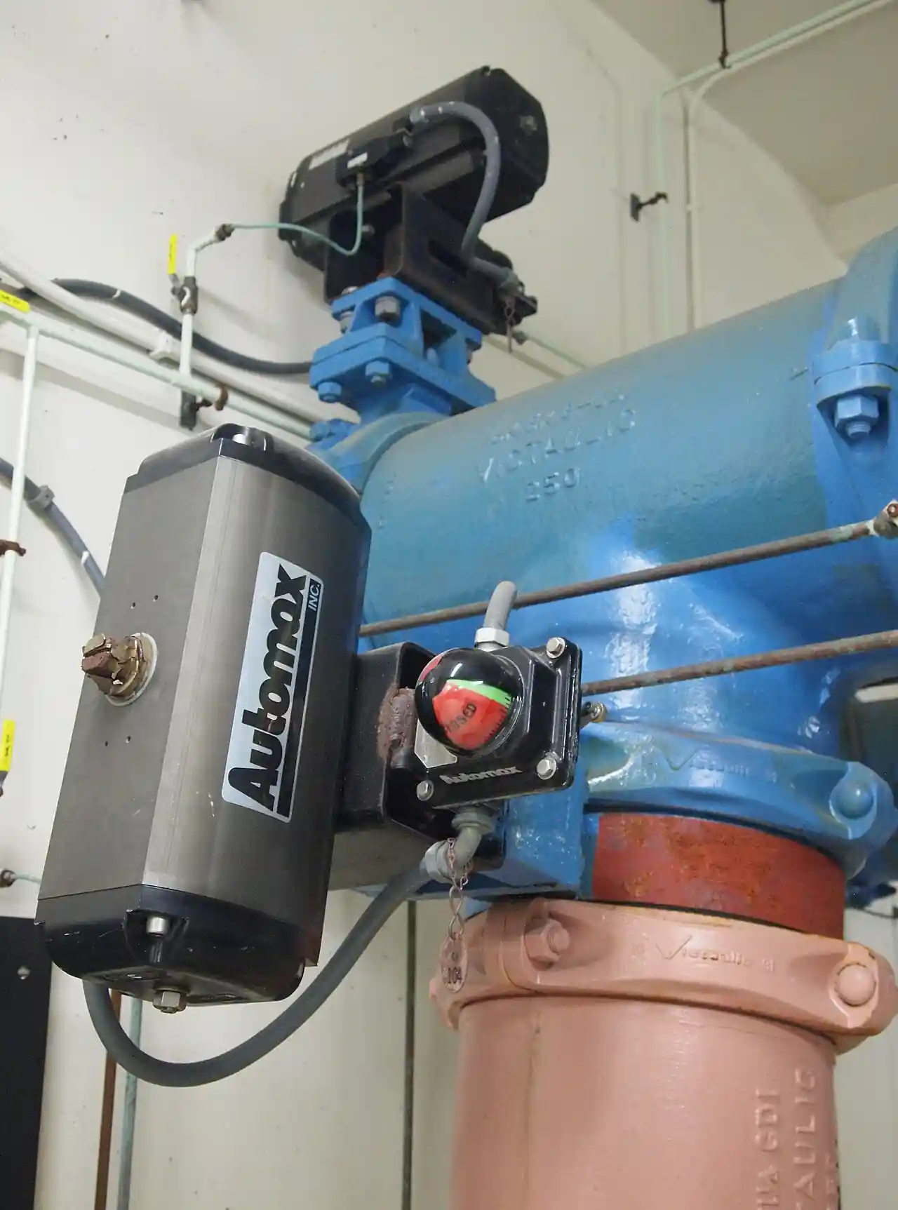
A pneumatic diaphragm actuator is a device that turns instrument air pressure into linear stem force. Air acts on one side of a large, fabric reinforced rolling diaphragm, a calibrated spring range opposes it, and the balance of the two moves a stem through a straight stroke. It is the linear muscle bolted to the great majority of globe bodied control valves, and its defining property is fail safe behavior without air: when supply is lost, the spring, not a controller, decides where the stem rests.
The procurement decision around this device is easy to get wrong because the actuator cannot be quoted alone. It is sized against the valve it drives: the unbalance force of the plug at worst differential, the friction of the packing, the seat load needed for the shutoff class, and the bench set that ties all of those to a spring preload. This page works those numbers in the open: force balance and thrust across the stroke, direct and reverse acting constructions, bench set practice, diaphragm and spring materials, fail action logic, positioner pairing, and the RFQ language that makes two quotations comparable. It is written for engineers who specify, not for readers who want a brochure.
This page decodes the pneumatic diaphragm actuator as a purchasing object: how the spring and diaphragm force balance produces stem thrust, why thrust falls as the spring compresses, what bench set really sets, which construction survives which service, and how fail action, positioner pairing, and air supply quality decide whether a quoted package will hold its seat in five years. It is written for engineers who must write a defensible RFQ, not for readers who want a marketing summary.
Chapter 1 / 06
What a Diaphragm Actuator Is and What Is Being Decided
Mechanically the device is short list of parts. A pressed steel casing, or two casings, clamps the edge of a molded diaphragm whose center plate ties to the stem. Beneath or above it sits a spring, or a stack of smaller springs, preloaded against the diaphragm plate. The stem passes through a yoke that also carries the connection to the valve bonnet, and on most modern units a valve positioner is mounted on the yoke reading stem position and metering air. Bolting that assembly to a globe valve body is what turns a valve into a control valve: the package, body plus actuator plus positioner, is the item being purchased.
What is actually decided at purchase is a system sizing, and four numbers carry it. First, fail action: spring direction, whether loss of air drives the stem to close, to open, or holds nothing because the unit is double acting. Second, bench set: the spring preload, expressed as the signal pressure span, commonly 0.2 to 1.0 bar, that takes the stem from one end of travel to the other, which fixes the seat load available at zero signal. Third, thrust margin: available stem force at minimum supply pressure against the valve unbalance force, with 1.3 times as the customary floor. Fourth, air supply quality and quantity, which decides whether the diaphragm and the positioner live out their design life.
Boundary against neighbors is worth one paragraph because mis-assignment is common. The diaphragm actuator is a linear machine with strokes up to about 100 mm; it is made for rising stem bodies. Quarter turn duties, a ball valve or a butterfly valve in shutoff and throttling service, are driven by rotary converters: the scotch yoke actuator and the rack and pinion cylinders that make up most of the rest of the pneumatic valve actuator population. Ordering a linear diaphragm unit and converting its stroke to 90 degrees through a lever and link wastes thrust to geometry and should be reserved for legacy installations, not new designs.
Prevalence explains why this page reads like a reference manual rather than a catalog of exotic options. Spring and diaphragm units are the most numerous control valve actuators in process plants: they are inexpensive, tolerant of modest air quality, inherently fail safe, and serviceable with a kit and a spanner. Their limits are equally plain: thrust ceilings and stroke ceilings. Beyond roughly 100 mm of travel, or where unbalance forces outrun the largest practical diaphragm area at the available supply pressure, other technologies take over, and chapter 5 draws that line explicitly.
The economics sit inside the control valve package rather than beside it. As a fraction of package price the actuator is usually the smaller number against the body and trim, but a wrong actuator selection invalidates the body: an undersized unit cannot reach shutoff class, and an oversized one on a small valve wastes both money and stroking speed. Retrofit and replacement demand is steady, since diaphragms and springs are consumables with twenty year fleet consequences, which is why spare parts pricing belongs in the original RFQ and not in the first emergency order.
Chapter 2 / 06
How the Spring and Diaphragm Force Balance Works
The operating principle is one sentence of physics: stem force equals signal pressure times effective diaphragm area, minus the spring force opposing it. With instrument supply normally between 1.4 and 4 bar and a positioner output to the diaphragm casing commonly spanning 0.2 to 1.0 bar, the area term does the heavy lifting: a diaphragm of 1000 square centimeters at 0.8 bar of casing pressure carries roughly 8000 newtons of gross force before the spring takes its share. Sizing tables are just that multiplication with the spring rate folded in.
Bench set is the calibration that makes the spring term predictable. Set on the bench with the actuator off the valve, it defines the pressure at which the stem just starts to move from one end and the pressure at which it completes travel: a 0.2 to 1.0 bar bench set means 0.2 bar overcomes the preload and 1.0 bar compresses the spring through the full stroke. The same figures, stated in the datasheet, fix the seat load at zero signal: for a fail closed, air to open unit, the difference between the preload force at zero signal and the valve unbalance is what presses the plug into the seat when the controller commands closed. A bench set chosen casually is a shutoff class chosen casually.
Thrust is not constant across the stroke, and the reason is the spring. As the stem travels, the spring compresses and its resisting force rises by spring rate times travel, so the net output force falls monotonically from start to end of stroke. For air to open actuators the minimum thrust sits at the open end, exactly where high pressure drop often wants the plug; for air to close units it sits at the seat, where shutoff needs it most. Suppliers publish thrust versus travel diagrams, and an RFQ should demand the diagram rather than a single worst case number, because the valve's unbalance force also varies with travel and the two curves must clear each other everywhere, not merely at the ends.
The diaphragm itself is an engineered component, not a flat sheet. A rolling diaphragm profile, with a convolution that rolls between the plate and the casing wall as the stem moves, keeps nearly the full area effective through the entire stroke and avoids the sharp fold line that fatigues flat diaphragms. Flat diaphragms survive at the small, cheap end of the market and in low cycle duty. The molding is fabric reinforced, typically nylon cloth vulcanized into the elastomer, and the edge clamping land, casing bolt pattern, and center plate pilot are the dimensional features that decide whether a replacement diaphragm fits.
Closing the loop turns the force machine into an instrument. Open loop, a regulator feeding the casing from the controller output moves the stem somewhere proportional to pressure, defeated by packing friction and hysteresis of several percent. Fitted with a valve positioner, the package compares commanded signal, classically 4 to 20 mA from the loop, with actual stem position measured by a linkage or a non contact sensor, and meters air to both sides of the balance until position matches command. Positioner quality, not actuator size, is what determines how well a control valve actually controls, a point chapter 5 returns to when pairing hardware.
Stroking time is the last number the force balance hands over. A large diaphragm casing holds tens of liters, and filling it through a positioner output orifice a few millimeters across takes time: full stroke in one to a few seconds on small units and tens of seconds on the largest casings is normal, and volume boosters cut those figures where trip logic cannot wait. Air consumption follows the same volumes, since every full stroke fills and then vents the casing once, which matters on plants where instrument air capacity is marginal.
Chapter 3 / 06
Types, Construction, and Duty Boundaries
Construction divides first by action. In a direct acting actuator, air pressure admitted above the diaphragm pushes the stem downward; paired with a globe trim that closes on downstroke, it gives air to close with spring to open fail action. In a reverse acting actuator, the casing arrangement inverts so air drives the stem upward, giving air to open and spring to close. The choice is not free floating: it is dictated by the valve's flow direction under the plug and by the fail action the process requires, and the body style must be stated with the actuator action or the quotation is ambiguous.
The second division is spring opposed versus double acting. The spring opposed, single acting unit is the industry default precisely because it is self contained fail safe: air on one side, spring on the other, and the failure mode written into the hardware. A double acting diaphragm or piston unit applies air to both sides and achieves higher force from the same envelope, but with no spring it has no defined failure position unless trip valves and accumulators are engineered around it, at which point the simplicity that justified the choice has been spent.
Spring architecture has quietly modernized. Classical designs used one large coil spring, preloaded by the upper casing position, which made bench set adjustment a two person job with a crane for large sizes. Multi spring stacks, six to twelve smaller springs acting in parallel, deliver the same rate in a flatter package and let bench set be set with shims or a calibrated adjusting nut. For the buyer the practical differences are envelope height, the repeatability of the bench set after maintenance, and whether the spring stack is a stocked item or a made to order one.
Materials set the environmental envelope. Casings are pressed or cast steel, painted, with stainless steel hardware available as an option line for coastal and washdown rooms; stems are stainless as standard, and yokes are cast iron or fabricated steel. Diaphragm elastomers carry the chemistry: nitrile rubber is the standard compound good for ordinary instrument air to roughly 80 deg C ambient, EPDM suits deionized water plants and hot, oil free air to higher temperatures, and high temperature fabric compounds serve bonnet heat that would cook standard elastomers. The diaphragm is the first casualty of compressor oil carryover, which is why air quality is an actuator specification item and not a plant afterthought.
Duty boundaries are concrete. Stroke ranges run roughly 14 to 100 mm across the size ladder, matching globe trims from small ANSI classes to DN 200 and larger bodies. Casing pressure ratings cover normal instrument supply with margin, and the RFQ should state maximum supply, not nominal, since some plants deliver 6 bar to the header and derate hardware accordingly. High vibration, subzero outdoor exposure with wet air, and corrosive hydrogen sulfide bearing atmospheres each push the specification toward options: reinforced diaphragms, space heaters, special coatings. The table below maps common duties to construction.
Duty
Suitable construction
Construction to avoid
General plant throttling, failsafe required, clean dry air
Spring opposed multi spring unit, NBR diaphragm, with positioner
Double acting unit without trip hardware
Fuel gas feed valve, must close on air loss
Reverse acting, air to open, spring to close, 1.3x margin on shutoff unbalance
Air to open with marginal bench preload
Cooling water valve, must open on air loss
Direct acting, spring to open, thrust checked at minimum supply
Spring range sized at nominal supply only
Outdoor coastal installation
Coated casings, stainless steel fasteners and stem, UV stable diaphragm
Standard painted hardware, zinc plated bolts
Hot service, bonnet heat above 80 deg C
High temperature diaphragm compound, extended bonnet
Standard NBR diaphragm at the bonnet
High cycle modulating duty
Rolling diaphragm, low friction packing, digital positioner
Flat diaphragm small envelope economy unit
Stroke above about 100 mm or very high thrust
Piston cylinder or electrohydraulic alternative
Diaphragm unit converted with lever and link
Quarter turn valve automation
Scotch yoke or rack and pinion rotary driver
Linear diaphragm unit with field built linkage
Chapter 4 / 06
Key Specification Parameters
The datasheet lines that decide whether a quoted actuator matches the valve are collected below; the paragraphs after the tables explain what a weak answer on each line looks like.
Attribute
Typical range or options
What it decides
Effective diaphragm area
roughly 200 to 2300 cm2 across maker size ladders
Gross force available at casing pressure; actuator size number
Stroke range
14 to 100 mm
Which valve bodies the size can drive, and travel class of the package
Bench set spans
0.2 to 1.0 bar typical; 0.4 to 1.2 and 0.2 to 0.6 alternates
Seat load at zero signal and spring preload the field must verify
Air supply
1.4 to 4 bar instrument air, stated maximum included
Thrust available at minimum credible supply, casing rating
Output thrust
hundreds of N small sizes to beyond 8 kN large sizes
Margin over valve unbalance plus packing friction
Fail action
Spring to close, spring to open, double acting
Process behavior on air loss; sizing direction of the spring case
Diaphragm material
NBR, EPDM, high temperature fabric compounds
Ambient and bonnet temperature, air oil content tolerance
Spring architecture
Single coil, multi spring stack
Envelope height, bench set repeatability, spare strategy
Interface standards
IEC 60534-6-1 mounting details; ISO 5210 and 5211 context for rotary
Interchangeability of actuator on valve across makers
Technology comparison belongs beside the key spec table because the first selection question is family, not size. The table below places the spring and diaphragm unit against the piston cylinder, the motor driven electric package, and the electrohydraulic module on the axes a buyer actually pays for: force for size, failure behavior, stiffness against flow forces, speed, and maintenance burden.
Technology
Thrust for size
Fail action
Stiffness
Speed
Notes
Spring and diaphragm
Moderate
Inherent, spring driven
Moderate, air compressible
1 to 10 s typical stroke
Cheapest fail safe; most numerous; stroke ceiling near 100 mm
Piston cylinder, pneumatic
High
Only with added spring module or trip valves
High
Faster
Needs clean air and always a positioner
Motor driven electric
Moderate to high
Battery or spring capstan options only
High when seated
Slower, by gear ratio
No air plant needed; wiring and duty cycle considerations
Electrohydraulic module
Highest
Accumulator engineered in
Highest
Fast
Highest cost and leak hygiene burden; large stems
Standards give the specification words fixed meaning. The IEC 60534 series governs industrial process control valves as a system, and its part IEC 60534-6-1 details the mounting of actuators to control valves, the interface a buyer relies on when mixing a valve body from one maker with an actuator from another. Where the same plant also buys rotary packages, the companion mounting standards ISO 5210 for multi turn and ISO 5211 for part turn define those interfaces, and the RFQ should cite the relevant part rather than the series alone. Bench set, seat load, and travel language should follow the definitions in IEC 60534 so that a factory certificate and a site acceptance check measure the same quantities.
The datasheet must state the load side as completely as the actuator side. Required lines: valve unbalance force at maximum differential, computed at the full pressure the upstream source can actually deliver; packing friction allowance by packing type and stem size; required seat load for the specified leakage class; stem diameter and travel; the shutoff differential the seat load must hold; bench set with tolerances; supply pressure range including minimum credible; fail action; ambient and bonnet temperature; and stroking time limits if the process trip logic depends on them. A quotation returned without thrust versus travel data and the bench range setting procedure is incomplete regardless of price.
Chapter 5 / 06
Selection Decision Factors and RFQ Language
The selection sequence runs as a checklist, and each step feeds the next a number.
Fix the fail action from process risk first: which position, open or closed, does the process need on air loss, at every valve in the loop.
Compute valve unbalance force at worst credible differential, including pump shutoff head, and add packing friction.
Apply thrust margin: require at least 1.3 times the computed load, evaluated at minimum supply pressure and at the worst travel position.
Select actuator size from thrust versus travel at the stated bench set, not from the size ladder name.
Set bench set so the spring preload delivers the seat load the leakage class needs at zero signal.
Choose the valve positioner: pneumatic, electro pneumatic 4 to 20 mA, or digital with diagnostics; add boosters where stroke volume is large.
Specify the air plant: regulator set point, FRL unitfiltration and dew point, oil free requirement for the diaphragm.
Verify both powered stroking time and failure stroking time against what the trip philosophy assumes.
Rotary duties need the redirect paragraph before any sizing. A ball valve or butterfly valve package is better driven by a scotch yoke actuator or rack and pinion cylinders, the mainstream of the pneumatic valve actuator family for quarter turn, because those convert cylinder force into torque directly. The diaphragm unit belongs on the rising stem of a globe valve, where its long gentle stroke and forgiving spring match the trim. Forcing either machine into the other's role through linkages is a legacy workaround, and new designs should not carry it.
Against the alternatives, the spring and diaphragm case is simple honesty about trade offs. A piston actuator is essentially a pneumatic cylinder optimized for instrument service: more thrust from a smaller envelope, but no inherent failure position without a spring return module, and stricter air cleanliness demands. An electric actuator removes the air plant entirely and wires neatly into modern networks, at higher purchase cost, slower stroking, and a fail position problem solved only by batteries or spring capstans on small sizes. The hydraulic valve actuator and its electrohydraulic cousins deliver the highest force and stiffness of all, for the highest cost and the burden of a hydraulic power unit with its leak hygiene; that is the choice for very large stems and severe service, not for a plant's routine throttling inventory. Choose the least machine that clears the checklist.
Signal and air infrastructure decide field reliability. The positioner takes the loop command, 4 to 20 mA from the PLC or DCS, and modern digital units return diagnostics, cycle counts, and deviation alarms over the same pair or over IO-Link where the site instrumentation standard supports it. Trip and interlock schemes vent casing air through a dedicated solenoid valve, and its voltage, orifice, and response time belong on the datasheet. Supply monitoring is cheap insurance: a pressure transmitter in the air header, or a simple pressure switch at the actuator regulator, alarmed to the control room, converts a silent air starvation event into a work order instead of a control upset.
Configuration (DN 50 globe package)
Actuation and accessories
Budget range USD
Standard failsafe throttling
Spring and diaphragm unit, NBR, pneumatic positioner
900 to 2,000
Standard failsafe throttling
Spring and diaphragm unit, digital electro pneumatic positioner
1,600 to 3,200
High margin shutoff service
One size larger actuator, multi spring, EPDM, positioner
2,200 to 4,500
High temperature bonnet duty
High temperature diaphragm, extended bonnet, positioner
2,800 to 5,500
Quarter turn equivalent duty
Rack and pinion or scotch yoke unit with positioner
1,200 to 3,000
The budget lines are planning figures for the actuation package only, exclusive of the valve body, and they move with size and options. The RFQ block itself should read: valve body size, trim, and flow direction under the plug; required fail action; maximum differential including credible upsets; required seat load or leakage class; computed unbalance and friction basis; required thrust margin, minimum 1.3 times; actuator action, direct or reverse; bench set with tolerance; diaphragm material against ambient and bonnet temperature; supply pressure range; positioner type, signal, and protocols; solenoid valve data if a trip scheme exists; stroking time limits; mounting per IEC 60534-6-1; and deliverables: thrust versus travel diagram, bench range setting procedure, diaphragm and spring kit part numbers with prices, and casing pressure rating evidence.
Two quotations are comparable only when both carry the same evidence set: the thrust versus travel diagram at the stated bench set, the failure stroke time, the kit part numbers with prices, and the sizing basis behind the 1.3 times margin. Where one bidder supplies diagrams and the other supplies adjectives, the price difference is not information about hardware. Insist on the numbers, file them with the loop documentation, and the day the duty changes the answer is a lookup rather than a reselection.
Chapter 6 / 06
Installation, Standards, Failure Modes, and Maintenance
Installation begins with the air. Mount the filter regulator and FRL unit close to the actuator, set the regulator to the value used in sizing, and verify dew point and oil content against the diaphragm specification before the loop is commissioned; a regulator set higher later, because the loop was sluggish, silently changes bench set behavior. Pipe the casing vents so that draining water cannot pool in low spots, keep signal tubing away from hot surfaces, and support the positioner and solenoid wiring to the terminal standards of the site. On large units, confirm lifting points and the access clearance for a diaphragm change before the loop is insulated and painted in.
Commissioning is a bench set verification exercise, not a sticker check. With the loop isolated, apply gauge pressure to the casing and confirm the start of travel and full travel pressures match the datasheet bench set; adjust per the maker procedure, on multi spring units usually shims or the calibrated nut. Stroke the package and record powered stroke time; then test the failure path by venting the trip solenoid valve and timing the spring driven stroke, which is the number the trip philosophy actually depends on. Align travel feedback switches if fitted, and log the positioner calibration points so drift over the first year is measurable rather than anecdotal.
Maintenance intervals follow duty. Throttling valves in continuous service deserve a quarterly positioner zero and span check against the PLC command record, an annual diaphragm and casing inspection, and a full kit replacement at the maker's interval or at the first sign of soft failure. Digital positioners convert this from calendar guessing to condition based work: cycle counts, friction trend, and deviation statistics accumulate in the device, readable over HART or IO-Link gateways, and a rising friction trend says the packing, not the actuator, is aging. Keep one spare diaphragm kit and one spring set per size on site for critical loops; the parts are cheap and the outage they prevent is not.
Failure modes are few and age related. Diaphragm rupture, from ozone attack, oil swelling, or simply two decades of flexing, announces itself as continuous air loss at the casing vent and a stem that cannot hold position under load. Spring relaxation drifts the bench set and shows up as leakage at shutoff long before anyone measures it; rebench on a schedule. Casing corrosion at weep holes and yoke corrosion at the pipe threads undermine structural hardware in wet rooms; stainless steel fastener option lines exist for exactly this. Stem scoring from overtightened packing leaks air and biases the force balance. Frozen condensate in winter splits casings that were piped with sags; and where the air plant cannot be trusted at all, the honest fix is migrating that loop to an electric actuator rather than fighting the same diaphragm every year, or to an hydraulic valve actuator where force requirements demand it.
Monitoring closes the loop over the fleet. A low air pressure alarm from the pressure switch or pressure transmitter at each regulator station, trended in the control system, catches supply decay before the thrust margin disappears. Partial stroke testing, either built into digital positioners or performed monthly by procedure, exercises stems against seizure on valves that otherwise sit open for years. Record keeping finishes the job: bench set values, kit part numbers, stroking times, and the IEC 60534 basis of the original sizing, filed with each loop, turn every future retrofit from an investigation into a lookup.
FAQ
What is bench set and who sets it?
Bench set is the spring calibration of a spring and diaphragm actuator: the casing pressure span, commonly 0.2 to 1.0 bar, that takes the stem from just moving at one end of travel to fully stroked at the other. It is set at the factory and verified at commissioning by applying gauge pressure off the valve. It fixes the seat load available at zero signal, so it belongs in the datasheet with tolerances.
How do I choose spring to close or spring to open?
Choose from process risk, not convenience. Ask what the process needs on total air loss: fuel and feed lines usually fail closed so flow stops, cooling and quench lines usually fail open so cooling continues. The answer fixes actuator action, direct or reverse, against the valve trim's flow direction. It must be stated in the RFQ because it changes the hardware, not just a setting.
How much thrust margin should I specify?
Require at least 1.3 times the valve unbalance force plus packing friction, evaluated at minimum credible supply pressure and at the worst travel position, not the best one. The margin absorbs spring relaxation, diaphragm stiffening with age, friction growth from packing wear, and supply sag. Buying one size up is far cheaper than discovering an actuator that cannot reach shutoff class after commissioning.
Why does available thrust fall as the valve strokes?
Because the opposing spring compresses as the stem travels, and its resisting force rises by spring rate times travel. Net output force therefore falls monotonically from start to end of stroke, while the valve's own unbalance force varies along its curve as well. Demand the thrust versus travel diagram and check that the two curves clear each other across the whole stroke.
When should I use a piston cylinder instead of a diaphragm actuator?
Use a piston cylinder when thrust or envelope demands it: it produces more force from a smaller package and strokes faster. The trade offs are no inherent fail action without a spring return module or trip valves, stricter air cleanliness requirements, and a positioner being effectively mandatory. For routine failsafe throttling up to about 100 mm stroke, the spring and diaphragm unit remains the cheaper and simpler answer.
What diaphragm material do I need?
Standard nitrile rubber suits ordinary clean instrument air to roughly 80 deg C ambient. EPDM suits hot, oil free air and deionized water plant atmospheres. High temperature fabric compounds are required where bonnet heat or ambient exceeds the elastomer limits. Oil carryover from lubricated compressors is the most common killer of nitrile diaphragms, so specify oil free air and verify dew point.
How do I detect a ruptured diaphragm?
The classic sign is continuous air flow from the casing vent, with a stem that drifts under load and cannot hold position at constant signal. Sites also alarm on supply pressure decay or on unexplained positioner output saturation. Replace with the kit part number, verify the bench set afterward, and check the air supply for oil or water, since contamination is usually why the diaphragm failed early.