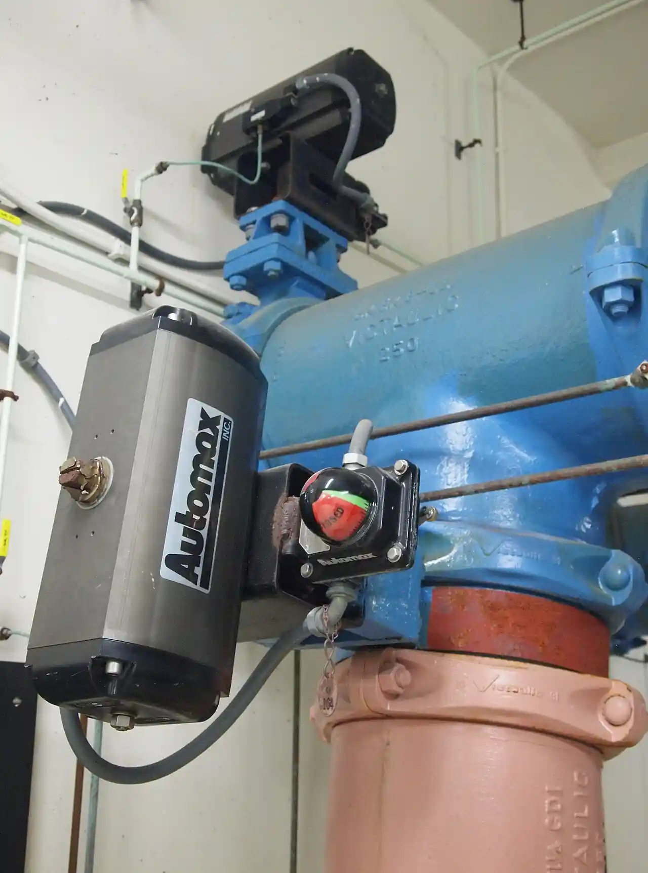
A hydraulic valve actuator converts pressurized oil, normally supplied at 70 to 210 bar, into the rotary or linear motion needed to stroke an industrial process valve. It is the high-force branch of the actuation family: where plant air at 6 to 8 bar runs out of torque and a geared electric drive runs out of speed or stiffness, hydraulic pressure acting on a small piston produces thousands of newton-meters from an envelope that a pneumatic cylinder of equal output would not fit into. This page is written for the engineer who specifies the actuator, not the one browsing it.
The pages in this encyclopedia cover the family in three leaves. The pneumatic valve actuator handles the volume market wherever an instrument air header already exists. The electric actuator serves isolated valves that can travel slowly. This leaf covers the hydraulic side: the four mechanism families a catalog actually sells, the materials and seals that set the temperature and fluid boundaries, a line-by-line decode of the datasheet, a worked sizing example on a DN300 Class 300 ball valve, and the installation and maintenance practice that carries a unit to its 1 million cycle rating.
The decision a specifier actually makes is narrow: how much torque at which points of the stroke, from what supply pressure, with what failure behavior, and inside what environment. Get those four right and the mechanism choice, the port size, and the price follow almost mechanically. Get one wrong and the valve stalls mid-stroke at maximum differential pressure, which is the most expensive possible way to discover an undersized actuator.
Chapter 1 / 06
What Is a Hydraulic Valve Actuator
Definition and job
A hydraulic valve actuator is a device that converts the energy of pressurized hydraulic oil into the rotary or linear motion required to stroke a process valve. On quarter-turn duties it delivers a full 90 degree rotation to operate a ball valve, a butterfly valve, or a plug valve. On linear duties it delivers thrust measured in kilonewtons to the rising stem of a gate valve, to a knife gate valve, or to a globe valve. In every case the actuator sits between two systems: a control system that commands position or direction, and a hydraulic supply that provides the force. The control side consumes watts; the power side consumes flow at pressure.
The selection problem is rarely whether a valve can be automated, because almost every industrial valve can be automated by some means. The problem is which power medium, which mechanism inside that medium, and which failure behavior together meet the torque demand, the stroke speed, and the shutdown requirement of one specific installation at a defensible cost. That decision, and the datasheet lines that encode it, is what the rest of this page is about.
Why specify hydraulic
Hydraulic actuation wins first on force density. Torque at the output shaft equals piston force times its acting radius, and piston force equals supply pressure times piston area. At 140 bar the hydraulic circuit carries roughly twenty times the pressure of a 7 bar plant air system, so the same force comes from a piston with about one twentieth of the area. A 300 Nm quarter-turn hydraulic unit fits in a body smaller than the pneumatic cylinder needed for the same output, and the advantage compounds with size: above roughly 2,000 Nm of break torque, pneumatic cylinders grow to impractical envelopes and the choice effectively narrows to hydraulic or electric.
The second advantage is stiffness. Oil is effectively incompressible at actuator pressures, so the actuator holds an intermediate position against flow turbulence, line pulsation, and load torque ripple without drifting or hunting. This is why modulating duties with hard dynamics, such as compressor anti-surge recycle and turbine bypass control, are frequently specified hydraulic. A pneumatic actuator working on a compressible medium can modulate well, but it needs a stiff positioner loop to reject the same disturbances, and its achievable bandwidth falls as cylinder volume grows.
The third advantage is stored energy. A charged accumulator or a preloaded spring cartridge can complete a full shutdown stroke after the total loss of pump power and control signal. That is precisely the behavior emergency shutdown (ESD) logic demands on pipeline block valves and compressor station vent duties, and it explains why hydraulic spring-return units are standard equipment there.
Where the selection question arises
Expect the hydraulic question to surface in five places. First, high-torque quarter-turn service: ball valves and butterfly valves above roughly DN200 operating at high differential pressure, where break torque climbs past what a multi-turn electric gear drive can deliver quickly. Second, subsea: at water depths to 3,000 m, hydraulic supply through umbilicals is a proven architecture, and hydraulic actuators dominate production tree and pipeline valves. Third, water control and hydroelectric plants: dam gates and penstock valves with torque demands from 50,000 Nm upward. Fourth, slurry lines, where pinch valves and diaphragm valves need steady high thrust rather than torque to squeeze the sleeve closed against abrasive solids. Fifth, ESD and blowdown service on oil and gas facilities, where the actuator must close against full line pressure after total utility failure.
For context, the pneumatic valve actuator remains the default wherever a 6 to 8 bar instrument air header already reaches the valve and torque demand stays below roughly 1,500 Nm; it is cheaper to buy, simpler to maintain, and intrinsically spark-free. The electric actuator is the default where neither air nor hydraulic infrastructure exists and travel times of 30 to 120 seconds are acceptable. This page assumes you are weighing the hydraulic option against those two siblings on a duty that stresses them, and it stays on the hydraulic side of the comparison.
Chapter 2 / 06
Working Principle and Actuator Types
The four mechanism families
Rack and pinion units place two opposed pistons in a single bore, each piston carrying a rack that meshes with a pinion on the output shaft. Pressure applied to one end cap drives both pistons as a pair and rotates the pinion a full 90 degrees; reversing the pressure reverses the rotation. Because the racks engage at a constant radius, output torque is nearly constant through the stroke and identical in both directions, which is the property a damper or a butterfly-style plug service wants. Hydraulic rack and pinion catalogs span roughly 100 to 6,000 Nm, mostly as double-acting units, with spring-return modules available as bolt-on extensions.
Scotch yoke actuators replace the racks with a yoke: one or two pistons slide a yoke plate whose curved track engages a roller or pin on an output crank. The geometry gives low mechanical advantage near mid-stroke and high advantage near the 0 degree and 90 degree ends, so the torque curve peaks exactly where a ball valve needs it: at breakaway, to wrench the ball off its seats against maximum differential pressure, and at the seating end, to force the ball into the seats for a bubble-tight shutdown. Spring cartridges stack alongside the piston for fail action. Catalog ranges span roughly 500 to 15,000 Nm with spring return, and engineered units for dam and waterworks service go far beyond.
Linear piston cylinders answer linear valves directly. A honed-bore cylinder with a hard-chromed rod bolts to a yoke bracket or couples straight to the stem of a gate valve in slurry and water service; on a knife gate valve the cylinder frequently replaces the handwheel as the primary operator, shearing the gate through the packed seat. Thrust ratings run from about 5 to 500 kN at 70 to 210 bar. A globe valve in modulating service pairs the same cylinder with a positioner for precise, repeatable travel control, and adjustable end cushions absorb the kinetic energy of fast strokes so the piston does not hammer the cap.
Vane actuators rotate a single vane fixed to the output shaft inside an annular chamber, sealed at the vane edges. They have the fewest moving parts of any rotary design, give constant torque, and occupy a very short envelope along the shaft axis; hydraulic vane ranges reach roughly 1,000 Nm. For the largest quarter-turn duties, a hydraulic motor driving a worm gearbox offers continuous rotation in both directions, lets the self-locking worm hold position when pressure is lost, and scales cleanly to the biggest damseal and waterworks valves, at the cost of stroke time.
Attribute
Rack and pinion
Scotch yoke
Linear cylinder
Typical hydraulic output range
100 to 6,000 Nm
500 to 15,000 Nm
5 to 500 kN thrust
Torque curve shape
Near constant through 90 deg
Peaks at both stroke ends, dip at mid travel
Constant thrust, no rotation
Best matched valve types
Butterfly valve, plug valve, damper
Ball valve at high delta P
Gate valve, knife gate valve, globe valve
Fail-safe arrangement
Optional spring modules, adds length
Integral spring cartridges, standard
External springs, counterweight, or accumulator
Relative envelope at 3,000 Nm
Baseline
Shorter and heavier
Longest, needs linkage
Relative purchase cost, double acting
1.0
1.15 to 1.3
0.9 plus linkage
Double acting versus spring return
A double-acting actuator uses hydraulic pressure for both directions of travel and, on loss of pressure, simply stays in its last position unless an external reserve is fitted. A spring-return unit carries one or more preloaded spring cartridges: on the powered stroke, hydraulic pressure compresses the springs; on a trip signal or total pressure loss, the springs drive the valve to its fail position, closed or open as specified. Two arithmetic consequences follow for the specifier. First, the powered stroke must overcome the valve torque and the spring back-drag together, which typically consumes 20 to 30 percent of the raw hydraulic torque. Second, spring output falls roughly linearly as the springs extend, so the spring torque curve must be checked at the end of the failure stroke, where the seating demand occurs, not at the start where the number looks best.
Accumulator fail-safe is the alternative for double-acting units. A 10 to 40 L bladder accumulator, charged to system pressure and isolated by a pilot-operated valve, stores enough oil for one or two complete strokes after pump loss. It suits fail-open or defined-position philosophies and avoids the size penalty of springs at high torque, but it depends on oil staying in the loop: a burst hose spends the reserve. A spring does not care about the hose.
Torque curves against the valve demand profile
Every quarter-turn valve imposes a three-part demand. Break torque opens it from seats and is the peak, set by seat interference and by the differential pressure across the closed ball or disc. Running torque carries the travel and is typically 30 to 50 percent of break. Seating torque closes the final degrees and rises again as the ball or disc wedges into the seat. The actuator torque curve must sit above the valve demand at every angle, evaluated at minimum sustained supply pressure, with margin. Scotch yoke and ball valve curves match naturally because both rise at the ends. A rack and pinion delivers flat torque, so its rating must simply exceed the break value; at high break-to-running ratios that flatness wastes envelope. Ask the valve manufacturer for the torque curve at your maximum differential pressure, not a single break number, and overlay the two curves before you commit.
Where the oil comes from: power units and control
The actuator is only half the machine. The other half is the hydraulic power unit (HPU): a reservoir of 40 to 400 L, a hydraulic pump driven by an electric motor, a relief valve set to the maximum working pressure, a return-line filter, and one or more accumulators, plus a directional control valve that routes oil to the actuator ports. One HPU skid can serve a dozen valves through a distribution manifold with individual isolation and bypass sets per valve. That shared-plant pattern is the economic standard in compressor stations and process units, because the pump, reservoir, and filtration cost are divided across every valve on the loop.
Where no such skid exists or ever will, the self-contained electro-hydraulic actuator integrates a small motor pump package, typically 380/400 V three-phase, a 2 to 10 L local reservoir, accumulator, and controls onto the actuator body itself. These units serve single valves on pipelines, waterworks, and remote well sites: no hose runs to leak, no shared oil to contaminate, and one power feed to terminate. The trade is a higher price per valve and local heat rejection, which matters in enclosed pits.
Control layers on top of the hydraulics. On/off duty uses a solenoid-operated directional valve, 24 VDC or 110/230 VAC coils, two-position for full strokes or three-position closed-center for defined intermediate holding. Modulating duty uses a proportional directional valve plus a 4 to 20 mA positioner: the loop closes locally in the actuator electronics, where a PID controller compares the command with shaft feedback and meters flow to the piston. A plant PLC only raises or lowers the setpoint over the current loop, which keeps field wiring to three or four cores regardless of valve size. Stroke speed is set independently by flow controls, so control quality and travel speed are decoupled; on a pneumatic positioner the two fight each other, and this separation is a genuine hydraulic advantage in modulating service.
Chapter 3 / 06
Construction, Materials, and Duty Boundaries
Housings and pressure-containing parts
Housing material follows size and environment. Extruded, hard-anodized aluminum, with an oxide layer of roughly 20 to 25 um, keeps small double-acting units light, typically through the 100 to 400 Nm class where weight on a small valve body matters more than burst margin. Above that class, working pressures of 140 to 210 bar push designs toward carbon steel castings such as ASTM A216 WCB, painted or epoxy coated, and toward 316L or duplex stainless steel for subsea and offshore splash zones. Offshore topside units are routinely specified with C5-M coating systems per ISO 12944 on the expectation of a first maintenance interval beyond 15 years.
The pressure-bearing cylinder bore is honed steel tube, typically E355 or ST52 grade, finished to an inner surface roughness of Ra 0.2 to 0.4 um and an H8 bore tolerance, because seal life tracks surface finish more closely than any other machined dimension. The rod is CK45 steel carrying a hard chromium layer 20 to 30 um thick, ground and polished to Ra 0.1 to 0.2 um, and protected at the gland by a wiper seal whose only job is to keep dirt on the outside. Stroke adjustment screws in the end caps, typically +/- 5 degrees per end on quarter-turn units, let the installer align the open and closed positions exactly with the valve seats instead of arguing with the coupling.
Spring cartridges are wound from shot-peened chrome-silicon steel bar, preloaded and guided to prevent coil buckling under compression. Piston and rod bearings are self-lubricating composite or bronze, selected to carry side load without galling after months of standing idle between strokes, which is the normal condition for an ESD unit. Fasteners on pressure caps are high-tensile and, on subsea and offshore builds, specified with material certification to the project's NACE or equivalent sour-service requirements when the process fluid contains wet hydrogen sulfide.
Seals, fluids, and temperature boundaries
Seal compound sets the fluid and temperature envelope. Nitrile (NBR) is the catalog standard, suited to mineral oil over roughly -30 to +100 deg C. Fluoroelastomer (FKM) extends the top of the range toward +200 deg C and is mandatory with phosphate ester fire-resistant fluids, which swell and destroy NBR. Low-temperature NBR compounds keep their elasticity down to -55 deg C for arctic sites. Water-glycol (HFC) fire-resistant fluid is workable but demands a specific seal, coating, and pump package; state the fluid in the RFQ and never let it be assumed.
The working fluid itself is normally mineral oil to ISO VG 32 or ISO VG 46. Catalogs allow a wide viscosity band, roughly 10 to 300 cSt, with 20 to 60 cSt optimal for pump life, valve metering, and seal lubrication. Viscosity bites twice in the field: a cold start can push oil past 300 cSt and starve the pump inlet, while sustained running above 80 deg C thins the oil toward the lower limit and accelerates oxidation, which is the root cause behind several failure modes in Chapter 6. Tank heaters and coolers are cheap insurance at both extremes; size them to the coldest and hottest soak temperature in the specification, not the daily average.
Duty boundaries: where each option stops being suitable
Ambient ratings of -40 to +80 deg C are standard across the industry. Low-temperature seal kits extend the bottom to -55 deg C, and high-temperature builds with FKM seals and widened clearances hold the top near +120 deg C for installations beside furnaces or in desert enclosures. Ingress protection runs IP66 and IP67 per IEC 60529 as routine outdoor ratings; subsea designs add qualified pressure-compensated enclosures tested at rated depth, with 3,000 m a common project boundary for tree and pipeline valve actuators. Explosion-proof motor and solenoid enclosures to IEC 60079 or the regional equivalent close the hazardous-area boundary, and the motor is the component that usually sets which certification limit you hit first.
Duty cycle separates the on/off and modulating product lines. An on/off actuator is rated for intermittent service, meaning a stated number of starts per hour at full pressure. Modulating service with up to 1,200 corrective travels per hour demands a continuous-rated pump motor, a proportional valve rated for high cycle counts, and position feedback designed for wear; buying a plain on/off unit for a modulating loop is a classic early-failure mistake that no margin calculation will rescue. The honest check is thermal: ask the vendor for the motor's duty rating and the pump's rated cycle count before accepting a modulating datasheet.
Stroke time is a flow problem, not a torque problem. Small quarter-turn units achieve 1 to 2 seconds; large ESD ball valves are deliberately slowed to 30 to 60 seconds or longer, both to protect polymer seats from slam and to keep liquid lines out of water hammer. Speed is set by flow-control valves in the supply lines, and the same valves provide the throttling needed to shape the last 10 degrees of closure. Manual override completes the boundary list: specify an integral hand pump or gear override for every valve that must operate during power loss, and state the acceptance number, for example full stroke within 150 hand-pump strokes by one operator, because a 2,000-stroke override is decoration, not a control.
Chapter 4 / 06
Key Specification Parameters
The datasheet for a hydraulic valve actuator compresses every preceding decision into roughly a dozen lines. The decode table below lists the lines that actually move a selection, what each one states, and what it decides for you. Ratings are comparable only at the same stated supply pressure: a torque number without a pressure beside it is not data.
Datasheet line
Catalog example
What it decides for you
Output torque, opening (0 to 90 deg)
2,800 Nm at 140 bar
Whether valve break torque is covered at minimum supply pressure
Output torque, closing (90 to 0 deg)
2,650 Nm at 140 bar
Seating coverage; spring back-drag shows up here
Supply pressure range
70 to 210 bar
Where you operate on the plant curve and the margin for pump wear
Stroke and adjustment
90 deg, +/- 5 deg per end
Matching the valve mechanical stops and seat alignment
Stroke time at rated pressure
2 to 8 s, flow-control adjustable
Process safety speed limits and water hammer control
Fail mode and spring torque
Fail closed, 3,600 Nm at spring end
Shutdown behavior at total pressure loss
Ports
2 x G 1/2 BSP
Flow ceiling, hose and manifold sizing
Fluid and viscosity band
ISO VG 46, 10 to 300 cSt
Seal compound, cold-start and hot-run behavior
Ingress and depth rating
IP68 per IEC 60529, to 3,000 m
Environmental qualification of the enclosure
Cycle life
1,000,000 full cycles class
Seal-kit and proof-test interval planning
Reading the torque lines
Output torque scales almost linearly with supply pressure: a unit rated 3,600 Nm at 140 bar delivers roughly 3,100 Nm at 120 bar. Recompute the duty point at the minimum sustained supply pressure, not the nominal one, because pumps wear, relief settings drift, and accumulators lose precharge. Closing torque is often 5 to 10 percent below opening torque because of spring back-drag or asymmetric piston areas; check both lines against the valve's break and seating values, and check them at minimum pressure.
The fail mode line deserves the most scrutiny on spring-return units. Ask for the spring torque at the end of the failure stroke and compare it with the seating torque of the valve at maximum differential pressure, keeping at least 25 percent margin even after the spring set has aged. Cycle life, normally quoted in a 1,000,000 full-cycle class, assumes rated pressure, clean oil per the stated ISO 4406 class, and no overload; halve your expectations for dirty oil or sustained maximum differential, and schedule seal kits accordingly.
Port size sets the speed ceiling. A G 1/4 port passes roughly 12 L/min and a G 1/2 roughly 30 L/min at actuator pressures, and the stroke time you can actually achieve is bounded by that flow, not by the actuator's torque rating. When a datasheet quotes a 2 second stroke, confirm which port and hose size that figure assumes, because the same unit on undersized hoses will not repeat it.
Control and signal options
Three control packages cover the market. On/off with limit switches or inductive sensors for open and closed indication, switched by a solenoid valve. Three-position with a closed-center spool for defined intermediate holding without continuous oil consumption. Modulating with 4 to 20 mA command and continuous feedback, closed locally by the positioner electronics. In modulating packages the position loop runs as a PID controller inside the actuator, and the supervisory PLC only sends the setpoint over the loop, so the specifier should verify loop tuning support for the process gain, not just the input and output ranges. Specify continuous 4 to 20 mA feedback rather than limit switches alone whenever the valve participates in any control or safety logic, because a proof test needs a measured travel value, not a contact.
Chapter 5 / 06
Selection Decision Factors
The decision sequence
Establish valve torque demand. Obtain break, running, and seating torque at maximum differential pressure from the valve manufacturer. Apply 25 to 30 percent margin, and add 10 percent more if the media scales, polymerizes, or carries solids, because seat friction grows between overhauls.
Fix the failure behavior. Fail closed, fail open, or last position, decided by process safety analysis, not preference. Fail action chooses the mechanism: spring return where independence from oil loss is required, accumulator reserve where stroke force or fail-open direction rules springs out.
Confirm supply availability. An existing HPU loop within reach changes the economics completely. No loop and multiple valves clustered means build one; no loop and a single valve points at a self-contained electro-hydraulic unit.
Set stroke time and duty cycle. ESD and on/off valves need a stated travel time with a stated tolerance; modulating valves need a continuous-rated package. Both need the water hammer check on liquid lines.
Qualify the environment. Ambient extremes, salt spray or submergence depth, hazardous-area classification, and sour-service exposure each eliminate product lines early. Filter the shortlist here, not after quoting.
Define the control signal. On/off contact versus 4 to 20 mA modulating with continuous feedback; add the PID loop expectations and the supervisory PLC interface before purchase, because retrofit electronics cost more than factory fit.
Specify manual override and feedback. Hand pump or gear override with an acceptance stroke count, continuous position feedback for any valve in logic, and the certification file: material certs, function test report, and the torque curve of the delivered unit.
Worked sizing example: DN300 Class 300 ball valve
Take a DN300 Class 300 ball valve on natural gas service with a manufacturer's break torque of 2,800 Nm at 51 bar maximum differential and a seating torque of 2,400 Nm. Applying a 25 percent margin to break gives 3,500 Nm required at the actuator output. The site supply is a 140 bar nominal HPU with a guaranteed minimum of 120 bar at the farthest takeoff. A scotch yoke rated 3,600 Nm at 120 bar therefore covers the duty with margin at both ends of its curve, because the scotch yoke torque peaks coincide with the valve's break and seating peaks; the mid-travel dip sits comfortably above the 1,100 Nm running demand. For fail action, a fail-closed spring stack delivering at least 3,000 Nm at the 0 degree end of the spring stroke (2,400 Nm seating plus 25 percent) closes the valve against full differential after total supply loss. This is the 3,500 Nm class selection the worked numbers point to, and it is deliberately conservative at the spring end rather than the pump end, because the spring is the energy source that cannot be serviced by anything but replacement.
Hydraulic versus the alternatives on the same duty
The mechanism and medium choice is only defensible when compared at the same torque, so the table below sets hydraulic against its two siblings on the 3,500 Nm duty of the worked example.
Attribute
Hydraulic
Pneumatic
Electric
Power medium and pressure
Oil at 70 to 210 bar
Air at 6 to 8 bar
380/400 V motor feed
Envelope at 3,500 Nm
Most compact rotary package
Very large twin cylinders and springs
Heavy gearbox, 100 to 180 kg class
Position stiffness
Stiff oil column, holds against pulsation
Compressible, drifts without positioner
Holds via brake or self-locking gear
Stroke time at high torque
2 to 60 s, field adjustable
1 to 3 s if oversized
30 to 120 s
Supply infrastructure
HPU skid or self-contained unit
Compressor, dryer, air header
Power feed and starter only
Fail-safe reserve
Springs or 10 to 40 L accumulator
Springs or volume tank
Springs or battery, limited
Modulating quality
Smooth, stiff, fast corrections
Workable with positioner
Precise but slow at torque
Main supply risk
Oil contamination and hose leaks
Air quality and freeze
Power outage, battery limits
Cost shape for the 3,500 Nm duty
Cost compares fairly only across the whole installation: actuator, shared plant, installation labor, energy, and upkeep. The figures below are indicative ex-works ranges for the worked 3,500 Nm duty and exist to show the shape of the decision, not to substitute for quotations.
Cost element
Self-contained electro-hydraulic
HPU-served valve
Pneumatic with volume tank
Actuator and controls, indicative
20,000 to 28,000 USD
12,000 to 16,000 USD
16,000 to 22,000 USD
Shared supply plant
None, integral
HPU skid 25,000 to 60,000 USD amortized over 5 to 15 valves
Volume tank and air header upgrades 5,000 to 10,000 USD
Installation per valve
2 to 4 days, power feed only
3 to 6 days, tubing runs
2 to 4 days, air lines
Indicative annual energy
300 to 800 kWh
1,000 to 3,000 kWh shared
2,000 to 5,000 kWh compressor load
Annual upkeep
Oil sample, filter, precharge check
Shared plus per-valve checks
Dryer and air quality upkeep
Best fit
Single valve, remote site, no utilities
5 or more valves clustered
Existing clean air plant at moderate torque
What to write in the RFQ
Valve data: size, class, type, and the manufacturer's torque curve at maximum differential pressure, not just a break number.
Required output torque with the margin basis stated, and the reference supply pressure, minimum and nominal.
Fail action, and for spring return the required spring torque at the end of the failure stroke.
Stroke time with tolerance, and the throttling requirement for the last 10 degrees of closure.
Ambient and storage temperature, ingress rating, hazardous-area classification, and submergence depth if applicable.
Fluid type and the target cleanliness class, ISO 4406 18/16/13 or cleaner, plus the filtration offered.
Manual override type and the acceptance stroke count.
Position feedback signal and the control interface expected from the PLC or DCS.
Certifications required: material certificates, function and hydrotest reports, and the delivered torque curve.
Chapter 6 / 06
Field Practice: Installation, Failure Modes, and Maintenance
Installation and commissioning
Cleanliness decides the first decade. New hose runs, tubing, and manifold ports arrive with manufacturing debris, and a fresh installation is the dirtiest the system will ever be. Flush every new run at normal velocity through a 10 um filter before connecting the actuator, and verify the oil against the target ISO 4406 18/16/13 class by sample, not by eye. Particles above roughly 5 um are the abrasive fraction that scores honed bores and embeds in seals; most of the cylinder wear a hydraulic actuator ever suffers is imported during commissioning.
Commission with the valve torque measured or logged through travel: record break at maximum achievable differential, running torque, and seating torque, and file the numbers as the baseline for every future proof test. Calibrate the 4 to 20 mA feedback at the electrical 0 and 100 percent points and verify the loop end to end in the supervisory system. Set damping before handover: throttle the last 10 degrees of closing travel on long liquid lines until the closure pressure transient is acceptable, because an uncontrolled 1 second closure on a 2 km water line can generate surge pressures tens of bar above working pressure. Confirm the mounting bracket and coupler alignment per the ISO 5211 interface, then torque the fasteners to spec and record them.
What goes wrong and how to specify against it
Internal piston seal bypass. The stroke slows under load, then stalls mid-travel with pressure equalized across the piston. The cause is worn or heat-hardened piston seals. Specify wear-resistant seal compounds and hold the cleanliness class; the repair is a seal kit, not a housing.
Spring fatigue. Cartridge free length and rate decay, on the order of 10 to 20 percent across a 10 year service life, so the fail stroke weakens where it matters, at the seating end. Annual torque testing on ESD units catches the trend while margin remains.
Rod and bore scoring. Contamination passing a failed wiper embeds in the rod surface and machines the bore with every stroke. Replace wipers at every seal service regardless of appearance, and keep the rod clean during outages.
Relief valve drift. The setpoint wanders low and the actuator stalls before full stroke, usually after the valve has been used as a speed control. Readjust to the datasheet setting and lock it, then set speed with the flow controls instead.
Solenoid spool sticking. Varnish from oxidized oil parks the spool between positions and the valve ignores commands. Trend oil acid number in the annual sample; varnish is predictable, and a spool that sticks in service was announcing itself in the lab results a year earlier.
Accumulator precharge loss. The first stroke after a long idle runs slow as bladder pressure decays. Check nitrogen precharge every 6 months, set to roughly 0.9 x the minimum working pressure, and log it against the hydraulic power unit's commissioning sheet.
Maintenance program
Run oil analysis annually: viscosity against the ISO VG grade, water content below 0.05 percent, particle count against the ISO 4406 target, and acid number trended year over year. Change the return filter element every 12 months or on its delta-pressure indicator, whichever comes first, and inspect the element for the debris signature that identifies the failing component upstream. Schedule seal kits at 5 to 8 years of service, or earlier on units that stroke daily, and replace springs as sets, never individually, to keep the torque curve symmetric.
ESD practice closes the loop between maintenance and safety. Stroke ESD valves monthly, with a partial stroke to about 80 percent open where full closure is not acceptable, and perform a full-stroke proof test every 6 to 12 months per the interval in the safety documentation. Record stroke time and spring torque at every test: a rising stroke-time trend is the earliest warning of seat scaling or seal wear while there is still margin to act. Keep the hand pump functional by using it during outages, verify local position indication against the remote signal quarterly, and retain the delivered torque curve with the maintenance file so the next engineer compares against the same baseline you commissioned against.
FAQ
When is hydraulic actuation worth it over pneumatic?
Above roughly 2,000 Nm of break torque, wherever plant air does not exist, and wherever the valve must modulate against strong load disturbances. A pneumatic actuator grows its cylinders with torque; at 3,000 Nm the hydraulic unit is typically a third of the envelope and holds position without hunting. If a 6 to 8 bar air header already reaches the valve and torque stays below about 1,500 Nm, pneumatic usually wins on purchase and maintenance cost.
How much torque margin should I add for scaling and seat aging?
Use 25 to 30 percent above the measured break and seating torque at maximum differential pressure as the baseline. Add a further 10 percent when the media scales, polymerizes, or carries solids, because seat friction grows between overhauls. On spring-return units, verify spring torque at the end of the failure stroke against seating demand, since spring output falls through travel and is the number that erodes first.
What fail-safe options exist without plant air?
Three. Spring return is the most independent: preloaded cartridges close or open the valve even on total oil loss, in catalog ranges to roughly 15,000 Nm. An accumulator reserve of 10 to 40 L stores one or two complete strokes of a double-acting unit after pump loss. A self-contained electro-hydraulic actuator with a local accumulator combines both ideas for single-valve sites. Springs keep working with a burst hose; accumulators do not.
Can a hydraulic actuator modulate a butterfly valve smoothly?
Yes, and it is one of the strongest cases for hydraulics. A proportional directional valve with a 4 to 20 mA positioner meters flow to the piston, and the incompressible oil column gives stiff mid-travel holding against the unstable torque a disc generates near 70 degrees open. Expect positioning within about 0.5 percent of span and up to 1,200 corrective travels per hour when the pump and valve are continuous-rated.
What oil cleanliness must the HPU maintain?
Target ISO 4406 18/16/13 or cleaner for on/off actuators, and 17/15/12 when proportional or servo valves meter the flow. Achieve it with 10 um return filtration, an offline kidney loop on reservoirs above about 100 L, and flushing of new hose runs before connection. Counts above target embed in seals and score honed bores; most of that wear is imported during commissioning, not generated in service.
How often do ESD hydraulic actuators need proof tests?
Follow the interval in the safety instrumented function documentation, commonly a full-stroke proof test every 6 to 12 months plus monthly partial-stroke tests to about 80 percent open. Record stroke time and spring torque at every test: a slowing trend flags seat scaling or seal wear while margin remains. IEC 61511 practice expects the test regime to come from the required risk reduction, not from vendor defaults.
Can I retrofit a hydraulic actuator onto an existing manual valve?
Usually, if the valve carries a standard part-turn mounting interface per ISO 5211 (flange and coupling dimensions) and its stem and bearings accept the drive loads. First measure the actual valve torque in place at working differential pressure with a torque wrench; aged seats can demand 50 percent more than new. Select against that measured value with margin, then confirm the bracket, coupler, and position indicator clear the pipework and insulation.