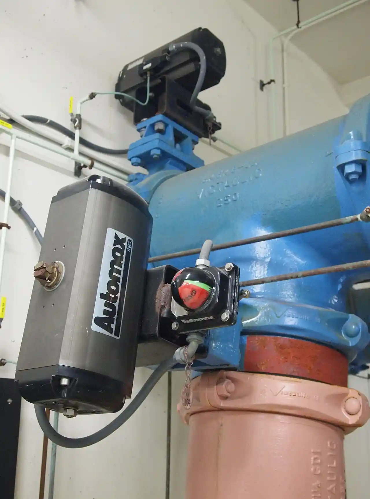
A rack and pinion actuator is the volume machine of quarter-turn valve automation: two opposing pistons, each carrying a straight rack cut, slide in a compact cylinder body and mesh with a central pinion, converting their linear thrust into a clean 90-degree rotation that opens and closes a ball valve, butterfly valve, or plug valve. Air pressure drives it, and the torque it delivers is constant across the entire stroke, because the rack pushes on the same lever arm from start to finish, which is the geometry that separates it from the scotch yoke actuator and its torque curve that peaks at the ends. It is pneumatic valve automation's economy product: sizes from a few newton-meters on small plastic-body units to several thousand on the largest stroking quarter-turns, spring-return or double-acting, mounted by the million on water, HVAC, and process plants worldwide.
Specifying one is five linked decisions: the torque demand of the valve at worst case, breakaway with the line's full differential and the seat aging margin, plus 25 to 50 percent safety factor, read against the actuator's torque table at the plant's worst supply pressure; the architecture, double-acting for speed and simplicity or spring-return for a defined fail position, with the spring cartridge consuming part of the air torque to close against; the interfaces, ISO 5211 mounting to the valve and NAMUR to the accessories, which make the assembly a bolt-together ecosystem instead of a fabrication project; the accessory stack, solenoid valve, limit switch box, positioner, manual override, in the order the loop demands; and the environment, temperature window, corrosion class, and hazardous-area certification that pick the body material and the variant. This page works each decision with catalog numbers and closes with the RFQ lines that make actuator quotes comparable at engineering level.
This page treats the rack and pinion actuator as a torque table with a bracket: constant-torque geometry, spring return versus double acting arithmetic, ISO 5211 and NAMUR interface discipline, accessory stacking and stroking speed, duty boundaries against scotch yoke and electric machines, and the RFQ lines that carry the specification.
Chapter 1 / 06
What a Rack and Pinion Actuator Is and What Is Being Decided
The mechanism is one sentence of mechanics. Two pistons sit back to back in a body, each carrying a rack geared into the central pinion; air on one side drives both pistons apart or together, and the racks rotate the pinion a quarter turn; reversing the air reverses the rotation. The output shaft, double-sided on most industrial bodies so the valve can be driven from either face, carries the torque to the valve through the ISO 5211 interface, and adjustment bolts at the end caps limit the travel a few degrees each way so the seats of the driven ball valve or butterfly valve are not hammered. The whole machine has four moving parts and wears only its seals, which is why the family's service intervals are measured in years and its price in hundreds rather than thousands.
What is being decided at purchase is the match between an actuator and a valve under the plant's worst air day. First, the torque demand: the valve's breakaway torque at maximum differential, published by the valve maker as a curve or table, inflated by seat aging, media deposits, and temperature, and then the safety factor, 25 percent as the common floor and 50 percent on severe service, all read against the actuator's torque table at the minimum supply pressure the plant will deliver in winter. Second, the architecture: double-acting cylinders deliver full torque both ways but hold no position on air loss; spring-return units dedicate part of their air torque to compressing springs so the stored energy can drive the valve to its fail position, closed or open, when the air or the solenoid signal dies, the fail-safe decision the hazard analysis owns. Third, the interfaces: the ISO 5211 flange and coupling dimensions, F03 through F25 by torque, that bolt the actuator to the valve, and the NAMUR interface, VDI/VDE 3845, that lets the solenoid and the switch box bolt directly on without tubing. Fourth, the accessories in their stacking order. Fifth, the environment: the body alloy, the seal kit elastomer, the temperature package, and the Ex certificate where the area demands.
The competitive frame keeps the selection honest. Against the scotch yoke actuator, the rack and pinion wins on price, on constant torque for valves that need torque everywhere equally, on compactness, and on availability, it is the catalog default of the industry; the scotch yoke wins where the valve's breakaway at end-of-travel dominates, high-pressure ball valves and large dampers, because its sine-shaped torque curve peaks exactly there, and it packages big spring energy more economically for heavy fail actions. Against the electric actuator, the pneumatic rack and pinion wins on speed, stroking in a second where the electric machine takes twenty, on price at equal torque, and on intrinsic safety in classified areas; the electric actuator wins where no instrument air exists and where the loop wants holding torque without consumption. Against the diaphragm actuator, there is little contest: diaphragms are for linear globe valves, and quarter-turn is this family's world. And the parent survey, the pneumatic valve actuator family page, carries the taxonomy and air-preparation discipline; this page carries the rack machine in depth, beside the scotch yoke leaf that carries its heavy-duty sibling.
One positioning note: this page is the single-product page for the rack and pinion machine. The pneumatic valve actuator family survey, the scotch yoke actuator, the electric actuator, and the valve positioner that converts any of them into a modulating element each have their own pages; here the assumption is a quarter-turn isolation valve to be automated on plant air, and every number that follows is chosen for that world.
Chapter 2 / 06
How Racks Convert Air Pressure into Constant Torque
The arithmetic is transparent, which is the family's virtue. Output torque equals air pressure times piston area times the pitch radius of the pinion, and because the rack tooth engages the pinion at a fixed radius through the entire stroke, the torque is constant from the first degree to the last: a size quoting 100 newton-meters at 6 bar delivers 100 newton-meters at every position. The torque table then scales linearly with pressure, and the honest selection reads it at the plant's worst supply, commonly 5 bar, not the catalog's flattering 7 or 8: the same actuator that gives 120 newton-meters at 7 bar gives 85 at 5, and the mismatch between catalog pressure and plant pressure is the oldest sizing error in the business.
Spring return changes the arithmetic in a defined way. The springs sit in cartridges behind the pistons; stroking against them, the air must both move the valve and compress the spring, so the air-side torque available at the valve is the bare piston torque minus the spring force at that point, and the fail-side torque is the spring force minus friction, delivered through the same constant-radius pinion. The datasheet states the result as paired numbers: spring torque at start and end of the fail stroke, and the air torque available at minimum supply pressure to overcome them, and the selection must verify both, the fail stroke torque against the valve's running and seating torque, and the air stroke against breakaway plus spring preload. Modular spring cartridges let the vendor tune the pair, and the RFQ's job is to state the valve's torque at three points, breakaway, running, and seating, so the pairing is engineered rather than guessed.
Architecture
Torque character
Fail behavior
Duty where it wins
Double acting
constant, full both ways
Holds last position on air loss
Speed, simplicity, torque economy
Spring return, fail close
spring curve minus friction
Drives valve closed
Default isolation safety
Spring return, fail open
spring curve minus friction
Drives valve open
Cooling and fail-flow lines
Double acting plus mid-travel fail
per design
Trapped-air logic position
Engineered last-position duty
Stroking speed is a flow problem, not a force problem. The actuator volumes on each side of the pistons must be filled and vented, and the speed is set by the air flow available: catalog figures run from a fraction of a second on the smallest units to several seconds on the largest, measured at nominal supply through a stated orifice. The levers are the solenoid's flow capacity, bigger Cv buys speed, the supply line size, a quarter-inch hose throttling a large actuator is a governor nobody ordered, and throttling valves in the ports when the opposite is wanted, needle valves that slow the vent to protect the pipeline from the actuator's own speed. Water hammer discipline on pumped lines is exactly here: a large butterfly valve slammed by an untuned actuator is the surge event the dual plate check valve page next door spends its life preventing.
The air itself is a specification input. The machine wants filtered, dry, ideally lubricated-per-maker plant air, commonly 40 micrometer filtration and a dew point below the coldest ambient, because the cylinder bores are finished surfaces and wet gritty air is lapping compound with a schedule. The air preparation unit, filter, regulator with gauge, and lubricator where the seal design expects one, belongs to the accessory list, mounted at the actuator, and the freezing winter failure of an undried supply is the most common actuator service call in temperate plants. Supply pressure windows run from about 2.5 bar minimum on torque-sized selections to 8 or 10 bar maximum by body rating, with 5 to 7 the practical band most plants deliver.
Chapter 3 / 06
Types, Construction, and Duty Boundaries
Construction divides by body material and by architecture. Extruded aluminum bodies, hard-anodized inside and out with epoxy or polyester coatings outside, are the industry standard: light, corrosion-resistant to the C4 paint class, and honest to about 120 deg C with the right seals. Stainless steel bodies, 316 or cast equivalents, serve offshore, coastal, chemical, and food-washdown duty where aluminum coatings surrender. Polymers and composites serve the small-size economy end. Pistons are aluminum or engineered polymer riding on the body bore; racks are hardened steel, pinned or integral to the pistons; the pinion runs in bearing-supported shafts, dual output shafts common so the valve drives from either side; end caps are aluminum, coated steel, or engineering polymer, carrying the adjustment bolts and the spring cartridges; and the seal kits are NBR standard with FKM for chemistry and temperature, specified as a kit line item because the kit is the machine's midlife. Temperature packages extend the standard minus 20 to plus 80 deg C window to minus 40 with low-temperature seals and grease and to plus 120 and beyond with high-temperature kits on some makes.
Architecture types were set out in Chapter 2's table: double-acting, and spring-return in both fail directions, with spring cartridge counts tuning the fail torque. Beyond those, the variants that matter are the interface and accessory executions. The NAMUR interface on the end caps, solenoid mounting pad and the switch-box slots on the body, makes the accessory stack bolt-on: the 5/2 or 3/2 solenoid valve, the limit switch box with mechanical, inductive, or proximity contacts, the pneumatic or electro-pneumatic positioner for modulating duty, all stacking without tubing runs. Manual overrides, lever or gear, and hand-wheel units, answer the maintenance question of how to stroke the valve with the air off. The Ex executions carry ATEX or IECEx certificates for the solenoid and switch combinations in classified areas, and the SIL-capable variants with certified switch boxes serve the safety-instrumented loop where the function demands the paperwork.
Execution
Typical envelope
Duty where it wins
Hard boundary
Aluminum double acting
about 10 to 7,500 Nm family-wide
General isolation automation
No defined fail position
Aluminum spring return
torque derated by cartridges
Fail-safe isolation, the volume duty
Spring torque ceiling
Stainless 316 body
by torque size
Offshore, chemical, washdown
Price and weight
NAMUR accessorized
bolt-on solenoid and switch
Everything engineered
Nothing, it is the standard
Positioner-equipped
0.2 to 1 bar or 4 to 20 mA
Modulating quarter-turn loops
Rangeability of the valve
Ex certified stack
ATEX or IECEx file
Classified areas
Certificate governs the stack
Manual override fitted
lever or gear
Maintenance access duty
Envelopes and cost
Duty boundaries, sentence by sentence. Quarter-turn isolation valves on plant air, ball, butterfly, and plug patterns to their torque ceilings: the rack and pinion owns the duty, full stop, it is the industry's default machine. High breakaway valves, high-pressure trunnion ball and large dampers: the scotch yoke actuator owns the ends-of-stroke torque peak and the heavy spring packages. No-air plants, remote pipelines, slow throttling with holding torque: the electric actuator owns the duty. Modulating loops at modest dynamics: the positioner-equipped rack machine serves honestly within the valve's rangeability; fast, characterized processes belong to the control valve world with its valve positioner and characterized trim. Subsea, high-temperature above 150 deg C, and hygienic drain-valve duty: engineered variants or other families by certificate. Each boundary is a torque-curve or energy-architecture statement, and Chapter 5 turns each into an RFQ line.
Chapter 4 / 06
Key Specification Parameters
The decode table is the datasheet skeleton. Every row is an RFQ line, and the two right columns are what each row decides and what it costs to leave blank.
Parameter
Typical catalog spread
What it decides
Torque rating at pressure
about 10 to 7,500 Nm family-wide
The whole sizing honesty
Architecture
double acting, spring return both directions
Fail position on air and signal loss
Supply pressure window
2.5 to 8 bar practical, 10 by body
Torque available on the worst air day
Stroke and adjustment
90 deg plus or minus a few, end bolts
Seat protection and alignment
ISO 5211 interface
F03 to F25 by torque
Valve mounting bolt-together
NAMUR accessory interface
VDI/VDE 3845 pads
Solenoid and switch stacking
Body and seal materials
anodized aluminum, 316, NBR or FKM kits
Corrosion class and chemistry window
Temperature package
minus 20 to plus 80 std, minus 40 to 120 kits
Site extremes and seal grade
Stroking time
fraction of a second to seconds by size
Process timing and surge behavior
Cycle life and duty
hundreds of thousands to millions
Maintenance interval economics
Certificates
ATEX or IECEx, CE, ISO 5211 and NAMUR conformity
Legal install and interface truth
The torque row is the one that separates engineering from quotation exchange. The honest line states the valve's torque demand at three points, breakaway at maximum differential, running, and seating, inflates by the aging and service factor, 25 percent floor, 50 percent severe, and reads the actuator table at minimum supply pressure; the dishonest line quotes the actuator's headline torque at 7 bar against the valve's catalog breakaway at zero differential, and the difference is the valve that will not move in February. For spring-return selections the check runs both directions: air torque against breakaway plus spring preload at worst supply, and spring torque at end of fail stroke against the valve's seating torque. A vendor answering the three-point torque statement with a size recommendation and the paired spring numbers is doing engineering; a vendor answering with a price is doing hope.
The interface rows decide whether the assembly is a bolt-together or a fabrication. The ISO 5211 flange letter fixes the bolt circle and the coupling square or star dimension to the valve stem; state the valve's interface in the RFQ or accept the vendor's bracket invention. The NAMUR pads fix the solenoid and switch mounting; a non-NAMUR body buys tubing runs and the maintenance complexity they carry. The accessory rows then complete the stack in order: solenoid valve, its function 5/2 or 3/2 and its voltage, limit switch box with the contact type the PLC wants, positioner where modulating, manual override where the maintenance philosophy demands, air preparation unit at the machine, and throttling needles where the pipeline wants the actuator slowed. Each accessory is a line item with a part number, and delivered-complete is the phrase that makes the assembly tested rather than assembled on site.
The environment rows price the decade. The corrosion class, C1 through C5-M in paint language, picks the coating package or the stainless body; the temperature window picks the seal and grease kit; the Ex area classification picks the certified solenoid and switch file, and the certificate governs the whole stack, not the components separately. The cycle life row reads honestly as duty: hundreds of thousands of cycles at rated torque on clean dry air is the family norm, and the service kit at midlife, seals and bearings, prices at a fraction of replacement. The certificate stack, conformity statements, Ex files, and the material certificates by project class, closes the delivery ticket; a quote missing the stack is not cheaper, it is later.
Chapter 5 / 06
Selection Decision Factors and RFQ Language
The decision sequence runs from the valve's torque outward, because every later step prices the earlier one.
Write the torque contract: valve make and size, breakaway, running, and seating torque at maximum differential and temperature, and the service factor the duty earns, 25 percent floor, 50 percent for severe seat aging, slurry-adjacent, or high temperature.
Fix the fail action as a hazard-review decision: fail closed, fail open, or last position; spring return buys the defined fail at a torque premium, double acting with logic buys last position at full torque.
Read the actuator table at worst-case supply, the winter pressure the plant actually delivers, and verify both strokes for spring return: air against breakaway plus preload, spring at end of stroke against seating.
Confirm the interfaces: ISO 5211 flange and coupling from the valve drawing, NAMUR pads for the accessory stack, and the bracket and coupling kit as part numbers, not shop fabrications.
Specify the accessory stack in order: solenoid function and voltage, switch box and contacts, positioner for modulating duty, manual override, air preparation unit, and the port throttles the pipeline study wants.
Match the environment: corrosion class to coating or stainless, temperature window to seal kit, Ex certificate to the area schedule, with the whole stack certified as the file demands.
Close with the commercial lines: torque table attached to the quote with the selected size marked, seal kit and spring cartridge part numbers, cycle life statement at the duty, delivery with the stack fitted and tested, and the warranty against the air quality spec stated.
The cost comparison is honest because the machine is simple. Against the scotch yoke at equal torque, the rack and pinion prices lower through the mid ranges and higher at the heavy spring end, and the crossover sits where breakaway-dominated valves begin, roughly the multi-hundred newton-meter high-pressure ball territory; below it the rack machine's constant torque is exactly what the valve wants and its price is the market's floor. Against the electric actuator, the pneumatic machine plus its solenoid and air preparation prices well under, strokes twenty times faster, and needs the air infrastructure the electric machine never asks for, so the plant's air answer decides the family before any datasheet opens. The maintenance economics: a clean-air rack and pinion is a seal kit at midlife and a decade of ignoring, and the accessories, solenoid coils and switch contacts, are the parts that actually fail; buying the stack from one maker with one file keeps the spare parts list to one page. Table the decision on cost per torque per decade including the air preparation and the kit, and the boundary writes itself.
Duty
Configuration to specify
Watch line
Water utility isolation valves
Spring return fail close, NAMUR stack
torque at winter supply pressure
HVAC butterfly isolation
Double acting or spring, compact sizes
stroke throttling for surge
High-pressure ball valve
Check scotch yoke crossover point
breakaway torque curve
Modulating quarter-turn loop
Positioner-equipped, characterized valve
valve rangeability floor
Offshore and coastal plant
Stainless body, C5-M package
certificate file completeness
Classified-area isolation
Ex certified solenoid and switch stack
certificate governs the stack
The RFQ language that makes quotes comparable, written as the datasheet lines a vendor must answer with numbers: torque at stated supply pressure for the selected size, both strokes for spring return with cartridge count; architecture and fail position; ISO 5211 interface size and coupling dimensions; NAMUR conformity; body, piston, and seal materials with the kit part number; temperature package; stroking time at nominal supply with the solenoid stated; accessory stack with part numbers fitted and tested; certificates; and the cycle life statement at the declared duty. A quotation answering those lines is a machine with a guarantee; anything else is a cylinder with optimism attached.
Chapter 6 / 06
Installation, Standards, Failure Modes, and Maintenance
Installation follows the interface discipline. Mount to the valve on the ISO 5211 flange with the coupling fitted to the stem flats, square, with the bracket bolts torqued and the travel adjustment bolts set so the valve's closed position lands on its seats without hammering; the few degrees of adjustment exist exactly for this, and skipping the setting is how seats learn their first bad habit. Bolt the solenoid and switch box to the NAMUR pads with their gaskets, wire the solenoid to its voltage with the plug polarity the LED wants, and set the switch cams so the closed contact trips at the actual closed position, verified by stem flat and by the line's proof test where one exists. Pipe the air preparation unit at the actuator, set the regulator to the design pressure with the gauge honest, and route supply lines short and one size generous; a throttled supply line is a slow actuator wearing a specification. Stroke the assembly ten times at commissioning, both directions at working pressure, and log the times; the numbers are the baseline every later service decision reads.
The standards frame is the interface world's own. ISO 5211 governs the valve mounting flanges and couplings; VDI/VDE 3845, the NAMUR standard, governs the accessory pads and the switch slots; the solenoid and switch world rides on the electromagnetic compatibility and low-voltage directives with ATEX or IECEx certificates for classified areas; the machine's own performance statements, torque tables and cycle life, answer the maker's conformity and the plant's functional-safety assessment where a SIL loop demands the file. None of this is exotic; the failure mode is an assembly bought mismatched, an actuator on a bracket somebody fabricated, accessories on tubing runs nobody drew, and the interfaces exist precisely to make that install impossible.
Failure modes arrive in a predictable order, and each has a specification answer. Undersized torque against aged seats shows as the valve stopping short or refusing to break at winter pressure: the answer is the three-point torque statement and the service factor at purchase, not a bigger regulator. Wet or dirty air shows as seal wear, bore scoring, and the slow stroke: the answer is the air preparation unit actually installed and drained, the dew point spec honored, and the lubricator where the seal design expects one. Frozen supply in winter shows as a dead actuator on the coldest morning: the answer is the dried air spec and, where the plant cannot deliver it, heat tracing the supply line or the low-temperature package. Spring cartridge fatigue on hot, high-cycle duty shows as a weakening fail stroke: the answer is the cartridge kit at the midlife service and the fail-stroke proof test on the annual schedule. Switch cam drift shows as false indications to the PLC: the answer is the commissioning cam set verified annually against the physical stem position. Solenoid coil failure shows as a valve that ignores its signal with everything else healthy: the answer is the spare coil in the stores kit, one per voltage, because it is the component that dies first and fixes in five minutes.
Maintenance is a small calendar honestly earned. Quarterly: air preparation unit drained and its filter condition noted, supply pressure at the design value, strokes timed against the commissioning record on a sample. Annually: switch and solenoid function proven, fail stroke proven on spring units with the air vented, mounting bolts and end-cap bolts re-torqued, and the exterior corrosion state of coated bodies noted against the C-class they were bought for. At midlife or by cycle count: the seal and bearing kit, the spring cartridges on demanding duty, and the bore inspected through the end caps; the machine rebuilds on a bench in an hour and kits price at a fraction of replacement. Keep one seal kit per size and one of each solenoid coil voltage in stores for the fleet; the rest is inventory theater.
The commissioning record closes the loop: as-built assembly with part numbers, torque selection basis with the three valve points, travel adjustment positions, switch cam settings, stroke times both directions at working pressure, supply pressure at the unit, and the certificates filed against the tag. One page per assembly, in the valve book. Plants that keep it stroke on evidence; plants that do not stroke on folklore, and folklore is slow.
FAQ
How much safety margin should I add to the valve torque?
Take the valve's breakaway torque at maximum differential and temperature, and apply 25 percent as the floor, 50 percent for severe duty, aged or scaling seats, high temperature, or slurry-adjacent service. Then read the actuator's torque table at the plant's worst winter supply pressure, not the catalog's flattering 7 bar. The mismatch between catalog pressure and plant pressure is the oldest sizing error in valve automation.
Double acting or spring return, which do I order?
Let the hazard review answer. Spring return delivers a defined fail position, closed or open, when air or the solenoid signal dies, and pays for it with part of the air torque spent compressing the cartridges, so both strokes must be checked. Double acting delivers full torque both ways, strokes faster, and holds last position on air loss, acceptable only where that failure state is engineered. Most water and process isolation duty orders spring return fail close.
Rack and pinion or scotch yoke for my ball valve?
Rack and pinion for constant torque demand through the mid ranges: it prices lower and its flat torque suits most ball and butterfly valves. Scotch yoke where breakaway at end of travel dominates, high-pressure trunnion ball valves and large dampers, because its torque curve peaks exactly at the ends and it packages heavy spring energy more economically. The crossover sits in the multi-hundred newton-meter high-pressure territory where the valve's torque shape decides.
What do ISO 5211 and NAMUR actually buy me?
Bolt-together engineering. ISO 5211 fixes the valve mounting flange and coupling dimensions, so actuator and valve from any conforming makers assemble without fabricated brackets. NAMUR, VDI/VDE 3845, fixes the solenoid and switch box mounting pads on the actuator, so the accessory stack bolts on without tubing runs. Both interfaces turn an assembly project into a parts list, and both belong named in the RFQ.
Why is my actuator slow even though the pressure gauge reads right?
Flow, not pressure: the actuator volumes must fill and vent through the solenoid and the supply line, and a small-Cv solenoid or a quarter-inch hose throttles a large cylinder regardless of gauge reading. Fit a solenoid with adequate flow capacity, size the supply line generously, and add port needle valves only where you want slowness, to protect the pipeline from the actuator's own speed.
Can a rack and pinion actuator do modulating control?
Yes within its envelope: fitted with a positioner, pneumatic or electro-pneumatic, the assembly throttles a quarter-turn valve on a 4 to 20 milliampere or 0.2 to 1 bar signal, and the HVAC and water industries modulate butterflies this way by the thousand. The honesty is the valve's rangeability, far short of a characterized control valve trim, so characterized processes belong to the control valve family with its own positioner discipline.
What maintenance does it need?
On clean dry air, almost none: drain and check the air preparation unit quarterly, time sample strokes against the commissioning record, prove the fail stroke annually on spring units, and fit the seal and bearing kit at midlife or by cycle count, an hour on a bench. The parts that actually fail first are the accessories, solenoid coils and switch contacts, so the stores kit is one coil per voltage and one seal kit per size. Wet, undried air converts this schedule into a rebuild calendar.