
An AC torque motor is a high-slip induction variant engineered to deliver rated torque at zero rpm without thermal runaway, and the continuous-stall envelope is the single most important number on its nameplate for any winding or unwinding station [S1][S2].
Standard induction motors will burn up under locked-rotor conditions; torque motors reach full torque at zero speed and dissipate I²R losses through a rotor designed for that exact service, typically run at 60 VAC or below for 100% duty cycle rather than nameplate 115 VAC [S1][S2].
Stall Rating and Thermal Envelope
Continuous-stall rating defines how long the motor can hold zero-rpm load at a given voltage before winding insulation reaches its class limit, usually 130°C for Class B or 155°C for Class F [S1][S2]. The Oriental Motor guidance is concrete: at 115 VAC the winding heats up quickly, while 60 VAC and below is the practical ceiling for uninterrupted stall service, with motor sizes typically capped at 20 W across the standard product line [S2].
Servo-motor terminology draws a sharper line: true continuous-stall torque is specified at a low reference speed, commonly 1 to 4 rps, not at absolute zero rpm, because a stationary synchronous rotor in still air has no convective cooling path and the drive's foldback current limit kicks in well before nameplate stall torque can be held indefinitely [S5]. For induction-type torque motors, the rotor's high-resistance design and the absence of aluminium cage bars are what allow continuous-stall operation without the rapid insulation degradation a standard induction motor would suffer [S2].
Voltage, Phase-Angle Drive, and Sizing Rules
Phase-angle SCR or triac control is the dominant voltage-modulation method, and a published 2026 sizing rule of thumb calls out 125% of motor full-load current as the minimum SCR controller rating, with a mandatory nameplate check on voltage, phase count, current, and stall torque before commissioning [S3]. The triac phase-control method on a TMP-1-class power controller, or any PLC analog output driving an SCR stack, is enough to vary winding tension without a position or velocity feedback loop [S2].
For DC excitation, the same physical machine converts to a brake: applying DC voltage stops rotation entirely and produces a voltage-proportional braking torque, which is the operating mode used in unwind stands where back-driven tension is the controlled variable [S2]. Designers should verify that the VFD or phase-angle stack can survive stall-current events, since direction reversals at full speed can pull upwards of 2x the rated stall current and a stopped-to-full-speed command can spike at the full stall-current value [S4].
Comparison: Torque Motor vs Induction Motor vs Servo for Winding
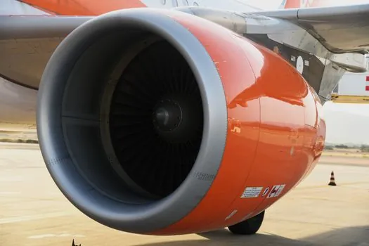
Three options compete for the same winder slot, and the decision matrix is sharper than the marketing suggests. An AC torque motor trades closed-loop precision for a simpler drive stack and inherent stall tolerance; a general-purpose induction motor running on a VFD is cheaper still but cannot hold stall torque without burning up; a closed-loop servo system gives the best dynamic response but requires diameter-tracking software, feedback devices, and a drive rated for peak current well above continuous [S1][S2][S5].
On four decision criteria: starting torque is high for torque motors, low for standard induction machines, and programmable up to 300% of rated for servo drives; speed adjustment uses a simple variac or phase-angle stack for torque motors versus a VFD for induction versus drive tuning for servo; stalled-operation capability is inherent for the torque motor, destructive for the standard induction motor, and limited to a few seconds for most servo motors under foldback; bill of materials drops to a contactor-plus-SCR for the torque-motor path, which is why it remains the default for low-cost film, tape, and label winding lines [S1][S2].
Application Mapping and Failure Modes
Winding and unwinding of paper rolls, plastic film, wire, cable, textile webbing, and metal strip is the canonical use case, with constant tension maintained as the reel diameter grows from core to full roll by trimming voltage to follow the changing load line on the speed-torque curve [S1][S2]. On a coiler, the same motor placed on the payout side runs in back-driven brake mode with DC excitation; on the take-up side, it runs as a motor with voltage tapering as diameter increases so the output torque, and thus web tension, stays constant [S1].
The most common failure mode is over-voltage stall, where a maintenance error or a sticky dancer position pushes the motor to 115 VAC nameplate voltage while the line is stopped, and the winding insulation degrades within minutes rather than the rated continuous-stall hours [S2]. A second failure pattern shows up when a phase-angle controller is undersized: inrush during a stopped-to-full-speed command can hit the full stall current, and a controller rated only for running current will trip its foldback or fail its SCR [S3][S4]. The Pololu engineering guidance to limit continuous current to 20 to 30% of stall current applies to general DC motors, but the principle translates: running a torque motor at the lowest voltage that still holds the load extends insulation life proportionally [S4].
Selection Criteria and Sizing Workflow
Start from the required web tension in N/m and the maximum full-roll diameter, compute the torque demand at the wind/unwind shaft, and then select a torque motor whose continuous-stall rating at 60 VAC meets or exceeds that torque with a 1.25 to 1.5 service factor for SCR controller sizing [S1][S3]. For single-phase lines, 110/115 and 220/230 VAC winding classes are standard, and built-in voltage-regulator terminal-box options remove the need for an external variac on simpler machines [S1][S2].
For a tension-control system built around a servo motor instead, the equivalent sizing exercise uses RMS torque over the cycle and a continuous-torque rating referenced to 1 to 4 rps, not the marketing "stall torque" number, which is a short-term peak in the servo world [S5]. Engineers retrofitting a constant-horsepower servo winding application from older literature should note that constant-HP tapering is a servo drive feature, not a torque-motor feature, and the torque motor instead follows a sloping torque-speed curve set purely by the applied voltage [S1][S7].
Standards, Sourcing, and Common Pitfalls
No single IEC or NEMA standard governs torque-motor stall rating, and OEMs publish continuous-stall torque, continuous current, and maximum allowable winding temperature directly on the nameplate; the engineering check is straightforward: nameplate voltage at stall, ambient temperature, and insulation class [S1][S2]. A practical acceptance test is to run the motor at its continuous-stall voltage into a locked rotor for the OEM-published duty cycle, then verify winding resistance has not drifted more than a few percent, which is a reliable proxy for insulation health [S1][S2].
For plants standardising on torque motors across multiple lines, the torque sensor on the load cell or dancer arm is the feedback element that closes the loop without a motor-mounted encoder, and a control cabinet layout that segregates SCR stacks from the analog dancer signal keeps electrical noise out of the tension readout. The most reliable upgrade path is to standardise on a single SCR controller family with documented 125% current margin and verified thermal performance at the actual continuous-stall voltage of the chosen torque motor [S3].
Track two signals over the next two quarters: phase-angle SCR controller releases with documented 125% continuous-stall current margin at 60 VAC, and torque-motor OEM datasheets that publish explicit continuous-stall duty at 60 VAC versus 115 VAC so the insulation-class derate no longer has to be back-calculated from generic induction-motor curves.
Background reading: ESD Grounding System Specs for SMT and PCB Assembly Lines.