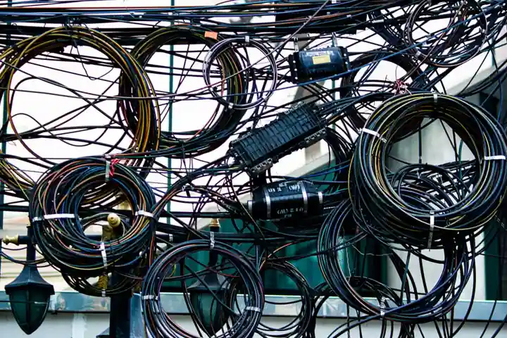
Most plant cables use organic polymer insulation (XLPE, EPR, PVC, CSPE) that embrittles, cracks, and absorbs moisture under combined thermal, radiation, and mechanical stress, and condition monitoring is the only practical way to manage thousands of kilometres of installed wiring without wholesale replacement [S1][S5].
The U.S. operating nuclear fleet alone contains thousands of miles of cabling, with the average unit at 39 years of service, and 91 reactors have already received licence renewals that push operating life to 60 or 80 years, which is why cable ageing management is now a regulatory and economic priority [S1].
Why Polymer Insulation Fails and What Monitoring Must Detect
Insulation ageing is driven by simultaneous exposure to elevated temperature, ionising radiation, humidity, vibration, and chemical attack; over time the polymer chains oxidise, the jacket hardens, and dielectric strength drops below design margin [S1][S5].
Field surveys consistently show that the failure mode operators encounter first is not conductor burn-out but insulation breakdown at splices, terminations, and bent sections, which is why a monitoring programme must combine global circuit diagnostics with localised physical inspection [S1].
Wholesale cable replacement in a mature plant is cost-prohibitive and can take critical circuits out of service for months, so the practical objective is trending: measuring an indicator of ageing, comparing it against an as-installed baseline, and estimating remaining useful life (RUL) instead of replacing on a fixed schedule [S1][S3].
Core Techniques: Reflectometry, LCR, IR, and LIRA
Time-domain reflectometry (TDR) injects a fast rise-time pulse and locates impedance discontinuities along a conductor, which makes it the default tool for pinpointing degraded splices, water trees, and shield damage on lengths from a few metres to several kilometres [S2].
Frequency-domain reflectometry (FDR) sweeps a band of frequencies and is more sensitive than TDR to small, distributed changes in insulation capacitance and loss tangent, which suits long HV cable runs where the damage is gradual rather than abrupt [S2].
Line Resonance Analysis (LIRA), developed by SINTEF and reported in April 2025, measures the cable's distributed inductance and capacitance to compute a "health index" that correlates with mechanical degradation of XLPE and EPR insulation, and the LIRA Power project now enables readings on energised power cables without taking them out of service [S9].
Insulation resistance (IR) testing with a 500 V or 1000 V megohmmeter, polarisation index (PI, the ratio of 10-minute to 1-minute IR), and dielectric loss-tangent (tan δ) measurements remain the baseline acceptance checks after any repair or re-termination [S2].
Integrated Online Monitoring Systems
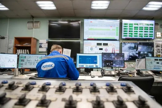
AMS Corporation's integrated cable condition monitoring platform combines TDR, FDR, LCR, reverse TDR (RTDR), waveform acquisition, current-to-voltage (IV) testing of nuclear instrumentation sensors, and IR into one rack-mounted system, and is designed to detect and pinpoint insulation, shield, and jacket faults in a single scheduled test pass [S2].
Online partial-discharge (PD) monitoring on medium-voltage feeders (typically 6–35 kV) uses HFCT or UHF couplers to pick up discharge pulses and report phase-resolved patterns, and Dynamic Ratings' cable monitoring product line applies the same continuous-monitoring principle to generator isolated-phase bus duct and station service cables [S6].
Rugged Monitoring's Power Cable Monitoring System focuses on real-time fault detection on critical feeders, embedding predictive analytics on top of distributed temperature and partial-discharge sensing so that the operator receives an alarm hours before a classical trip event [S8].
For control and instrumentation loops, the same architecture extends through cable condition monitoring to the broader condition monitoring system layer that ties cable health into plant-wide asset management dashboards.
Selection Criteria: Which Method Fits Which Cable
Cable type and voltage class drive method choice: low-voltage (≤1 kV) control and instrumentation cables are best handled with LCR plus TDR because the short lengths and small conductors make FDR resolution hard to exploit [S2].
Medium-voltage (6–35 kV) power cables are the natural home for online PD and distributed temperature sensing, since the ageing signals (micro-discharge, hotspot growth) are too small to see on a one-shot TDR test [S6][S8].
Long HV transmission and subsea cables benefit most from FDR and LIRA, because the distributed nature of water-treeing and thermal ageing needs a swept measurement, not a single pulse [S2][S9].
Quick comparison across the four dominant methods:
1. TDR: best for fault location and splice integrity, moderate cost, single-ended connection, poor sensitivity to distributed ageing.
2. FDR / LIRA: best for distributed ageing and trend monitoring, requires known cable parameters, higher upfront analysis cost.
3. Online PD (HFCT/UHF): best for MV/HV in-service monitoring, continuous data, requires couplers installed at known joint locations.
4. IR / PI / tan δ: best as commissioning and post-maintenance acceptance tests, simple instrument, no fault-location capability.
Standards, Ageing Models, and Remaining Useful Life
The IAEA TECDOC on benchmark analysis of condition monitoring techniques for aged low-voltage cables in nuclear power plants provides the international reference framework for selecting tests and trending data against qualified baseline values [S4].
Arrhenius-based thermal ageing models, combined with dose-rate radiation exposure data, let an operator extrapolate the insulation's elongation-at-break (a key mechanical proxy) toward an end-of-life threshold, and this is the basis of the "remaining useful life" outputs that cable monitoring software reports [S1][S3].
The September 2026 University of North Texas / INL summary of cable condition monitoring techniques explicitly groups the field into four families: electrical tests (TDR, FDR, LCR, IR), mechanical tests (indenter modulus, elongation), chemical tests (oxidation induction time, Fourier-transform infrared spectroscopy), and physical inspection, and recommends combining at least two families for any safety-significant circuit [S7].
Workmanship quality at terminations and joints controls the dominant failure probability for most low-voltage cable circuits, so on-site visual and thermographic inspection is treated as a first-class technique, not an add-on [S1].
Where Cable Monitoring Pays Off and Where It Does Not
Strongest return on investment: nuclear plant licence-extension programmes, offshore wind collection arrays, and critical MV feeders in continuous-process plants (refineries, chlor-alkali, aluminium smelters), where a single cable failure can cost more in lost production than ten years of monitoring [S1][S3][S6].
Limited or negative return: low-voltage, easily replaceable branch circuits in non-critical building services, where the labour cost of disconnecting, testing, and re-terminating exceeds the replacement cost of the cable itself.
Cable monitoring also feeds upstream into vibration condition monitoring and power monitoring system strategies, because insulation degradation almost always shows up as harmonic distortion, neutral current drift, or increased frame vibration on motor cables before it produces a hard fault.
Adjacent physical-layer monitoring such as cable gland integrity checks and cable tray fill-rate audits closes the loop, since a sound cable in a corroded, over-filled tray is still going to fail mechanically long before its insulation ages out.
Limits, Failure Modes, and Open Engineering Questions
Reflectometry methods need a known cable model (characteristic impedance, propagation velocity) to translate a reflection into a distance, and a wrong model produces a wrong location, which is why baseline as-installed measurements are mandatory, not optional [S2].
Online PD on long MV feeders suffers from noise contamination from variable-frequency drives and switch-mode power supplies, and a typical installation requires tuned band-pass filters and pulse-pattern recognition to keep false-positive rates below roughly 1–2 events per day per coupler [S6].
LIRA and similar distributed methods are still calibrated against accelerated-ageing laboratory data, so the empirical correlation between LIRA "health index" and field end-of-life is being actively built up; users should expect to maintain a parallel mechanical-sampling programme on a small population of retired cables until the correlations mature [S9].
Trackable signals for the next 6–12 months: wider rollout of the LIRA Power in-service measurement method to energised transmission cables, integration of cable health data into IEC 61850-based substation dashboards, and harmonisation of the IAEA TECDOC benchmarks with the IEEE nuclear-power cable ageing guidance so that plant programmes can use a single trending database across both frameworks.
Related analysis: Sheet vs Liquid-Applied Waterproofing: Decision Matrix.