Carbon fiber manufacturing is a two-stage supply chain: upstream fiber conversion from a polymer precursor (PAN, pitch, or rayon), then downstream composite part fabrication from those fibers. PAN-based fibers hold the dominant share of high-performance structural production, while pitch-based fibers serve specialty high-modulus and thermal-management applications [S2].
For a design engineer, the binding spec is the fiber itself: tensile strength, tensile modulus, filament count (1K, 3K, 6K, 12K, 24K), tow size, and surface treatment chemistry. Those numbers are fixed at the precursor line; downstream composite forming (prepreg-autoclave, resin transfer molding, filament winding, pultrusion) can only preserve or dilute the upstream values, not exceed them [S2][S5].
Precursor Selection and PAN-Limited Cost Structure
PAN-based carbon fibers have dominated the industry for decades, but the high cost of polyacrylonitrile has prevented the widespread adoption of carbon fiber in high-volume structural applications [S5]. The same source documents active research into polyamide-6-derived carbon fibers as a lower-cost precursor route, with microstructural evolution tracked across the thermal conversion stages [S5].
Pitch-based fibers split into two branches: isotropic pitch for general-purpose grades and mesophase (anisotropic) pitch for ultra-high-moduli grades above 600 GPa, which are specified for space structures, satellite booms, and high-stiffness tooling. Rayon-based fibers are largely a legacy route retained for ablative and heat-shield applications. For most engineers outside of carbon-carbon ablatives, the practical choice collapses to PAN vs. mesophase pitch on a stiffness-versus-cost basis [S2].
Thermal Conversion: Stabilization, Carbonization, Graphitization
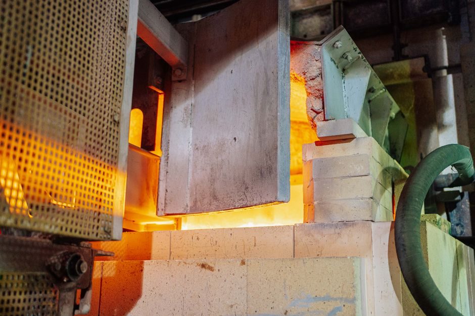
The PAN-to-carbon thermal sequence is fixed by chemistry, not preference. Precursor filaments are first oxidatively stabilized in air at 200-300°C, where the linear PAN ladder-polymerizes into a cyclized, non-melting structure capable of surviving higher temperatures; this stage typically runs 30-90 minutes and accounts for a significant share of line energy. The stabilized tow then passes through low-temperature carbonization at 400-900°C in nitrogen to drive off hydrogen, oxygen, and nitrogen, followed by high-temperature carbonization at 1000-1500°C for standard-modulus grades [S2][S5].
For high-modulus grades, a further graphitization step at 2000-3000°C aligns the turbostratic carbon crystallites along the fiber axis. Surface treatment (electrolytic oxidation) and a polymeric sizing are applied in-line at the end of the line to improve fiber-matrix adhesion and handling. The combined conversion burns off roughly 50% of the precursor mass, which is the root cause of the cost gap between carbon fiber and its precursor [S5].
Downstream Composite Forming: How Engineers Build Parts
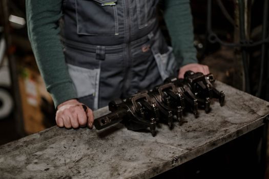
Prepreg and autoclave processing remains the default for primary aerospace structure. Pre-impregnated unidirectional tape or woven fabric is laid up ply-by-ply on a tool, vacuum-bagged, and cured under 0.3-0.7 MPa external pressure in an autoclave at 120-180°C for standard 120°C-cure epoxies, or at 175-200°C for toughened aerospace systems. A typical premium-class composites shop runs its own autoclave, CNC trimming cells, and paint shop in one integrated line to control scrap and surface quality [S6].
For larger structures and higher throughput, resin transfer molding (RTM) and vacuum-assisted resin transfer molding (VARTM) inject a low-viscosity resin through dry fiber preforms under vacuum (VARTM) or closed-mold pressure (RTM). Out-of-autoclave (OOA) prepregs paired with vacuum-bag-only cures close the cost gap for secondary structures and wind blade skins. For discontinuous-fiber and metal-matrix applications, short carbon fiber reinforced Al matrix composites can be produced preformless via liquid infiltration, bypassing the binder-bound perform step used in conventional MMC routes [S4].
Process Selection: Cost, Volume, and Mechanical Targets
Selection is not a single decision but a stacked one. Prepreg-autoclave gives the lowest part-to-part variability and the best mechanical properties, but capex on a qualified autoclave (typically rated 0.7-1.4 MPa and 200°C+), tooling, and long cure cycles drive cost up. VARTM and RTM cut capex and tooling cost, at the price of higher porosity risk and tighter permeability control. Short-fiber compression molding of carbon fiber reinforced thermoplastics delivers high volumes and net-shape parts at a few seconds of cycle time, but mechanical performance is bounded by fiber length and orientation distribution [S4][S6].
A practical spec gate for selection: if the part must meet aerospace primary-structure allowables (e.g. strain allowables around 0.3-0.4% for tension, with tight B-basis knockdowns), prepreg-autoclave is non-negotiable; if the part is a secondary bracket, a fairing, or a cover, OOA or RTM typically passes muster; if the part is a high-volume bracket or housing, compression-molded short-fiber thermoplastic is the economic answer [S6]. Material selection behavior for these metal-matrix and carbon-reinforced routes also ties into broader composite forming and steel replacement choices that engineers weigh on a property-per-dollar basis.
Process-Induced Distortion and the Tolerance Problem
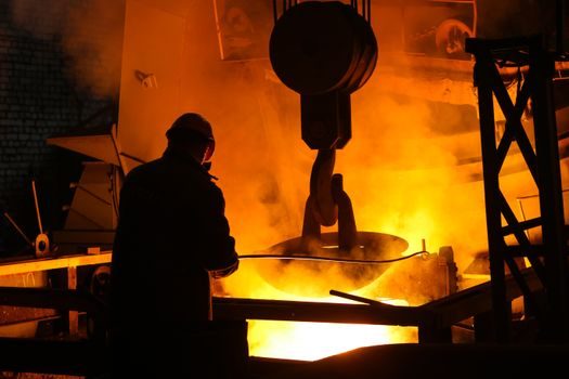
Residual stresses and shape distortions occur during the manufacturing of carbon fiber reinforced plastics, and analytical or numerical models are required to predict them accurately across large-scale production [S3].
For large aerodynamic surfaces and wind blade shells, the layup sequence, the cure cycle ramp rate, and the selection of an invar or composite tool versus an aluminum tool dominate the final geometry. Virtual compensation via FEM spring-in prediction is a standard practice; the failure mode of ignoring it is a post-cure trim step that cuts into structural ply and triggers B-basis knockdowns [S3].
Standards, Sourcing, and What to Verify on the Datasheet
For procurement, the binding documents are the manufacturer datasheet values for tensile strength (typically 3,500-7,000 MPa for standard-modulus PAN), tensile modulus (230-700 GPa depending on grade), density (~1.75-1.95 g/cm³), filament diameter (5-7 µm typical for PAN), and sizing chemistry. Aerospace prepreg material is typically accepted with certificate of conformance per AS9100, with the upstream fiber batch traceable to the precursor line [S1][S6].
Verify three things before sign-off: tow size and filament count match the layup design (a 12K tow cannot be substituted for a 6K tow without ply-thickness rework); sizing is compatible with the chosen resin chemistry (epoxy-compatible vs. polyester-compatible vs. polyurethane-compatible); and the areal weight and resin content of the prepreg are inside the qualified envelope, not just on the marketing datasheet. For specialty parts where the layup count or resin system differs from a previously qualified build, a new material allowables test program is the only path that survives an aerospace audit [S1][S6].
Trackable signal to watch next: polyamide-6-derived carbon fiber pilot lines reporting mechanical allowables and line speed in 2026-2027, which is the nearest credible challenger to the PAN cost ceiling [S5]. Adjacent adoption of short-fiber reinforcement in concrete and industrial mix design is on a parallel trajectory on the infrastructure side, with similar cost-versus-property trade-offs shaping which formulations ship in 2026 production.
For component-level specifications, see carbon fiber, additive manufacturing material, and carbon steel.